
High-end propeller clock [120732]
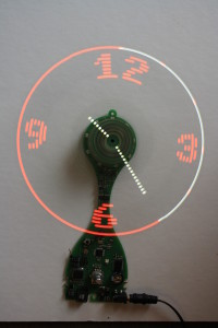
Buy it here!A propeller clock, also known as a Persistance Of Vision (POV) display is based on a mechanically moving led row. This led row is either oscillating or rotating at a rate superior to human's eye remanence, making a dot matrix which seems to float in the air.
A propeller clock, also known as a Persistance Of Vision (POV) display is based on a mechanically moving led row. This led row is either oscillating or rotating at a rate superior to human's eye remanence, making a dot matrix which seems to float in the air.
I've already built two of them, but they were only prototypes used to validate some technical solutions. Now I want to concretise these two tries into a fully fonctionnal system, which I could use in my living room 24h/24. To attain this goal, the system has to be silent and not subject to wear.
You'll find many similar projects on the web, but many of them are only table prototypes. I want to overtake this status and design a high-end system. But of course, the system has to be feasible by the most of us even with limited mechanical tools or skills.
The design is based on a hard disk drive brushless motor. Those parts are designed to be really silent and able to run for long periods.
The rotating board is a 20cm long 2-blades propeller, each of them containing 25 bicolor leds. This design has the advantage of beeing naturally balanced and offering a double refresh rate. On my previous prototype, i found that the propeller had to run at more than 3000t/min to offer a sufficient refresh rate, but this made air noise. With this double refresh, I'll be able to reduce at only 1500t/min without any flickering effect. The propeller contains 2 infrared sensors at each extremity to give a mechanical position reference. This propeller is then able to display a 25*128 dot bicolor round matrix.
The question of powering this rotating part is a big deal on those kind of systems. Some of them use batteries (no for me, thanks) or rotating brushes, which are of course incompatible with wear and noise requirements. On my previous system, I used a rotating transformer design wich worked great ! The secondary is wound on the motor's hub, rotating with it. The primary is wound a bit larger, but is static. This rotating transformer is then used in a simple flyback power supply... The power transmitted is enough to power all leds, even if efficiency is a bit weak... For this design I plan tu use a push-pull transformer, more stable in an open loop regulation. I guess winding a transformer could frigthen some of you, but I managed to do this, you'll be able too ! It only needs patience, adhesive tape and cyanoacrylate glue...
Some of similar projects embbed the Real Time clock on the rotating part... But this is a bit tricky when you need to set it up. To answer the noiseless requirement, I think the rotating part has to be lighter as possible, so I chose to let most of parts on static board, such as RTC, switches... The base board will be responsible of powering the motor, driving the transformer, keeping time and... telling the propeller what to display... To communicate between the base board and the rotating one, I succesfully used an infrared transmission with a phototransistor rotating with the propeller just above an 9 infrared led circle.
Update 14/11/2012 : Transformer winding
I've spent my last evening winding the secondary of the rotating transformer on the rotor of the brushless motor. I used 0.56mm enamelled copper wire. I was able to make 10 turns on first layer and 9 on the second one. Those 19 turns form one half of the secondary, 19 more turns needs to be added to complete the winding... But finally, instead of using two secondaries, i will only use this one on the push-pull converter and use a full diode bridge to redress output voltage. Simulation is still ok, showing a 18V voltage at low load and falling to about 8V with 3.5W load. That's more than needed...
I also made power estimation... I realised i forgot the snubber circuit for the mosfets. Even if currents are weak, the added snubber significantly reduces power loss in the transistors...
I finally added a small current monitoring resistor in series with one of the mosfets, it will help to visualise switching current during tests.
Photos of the transformer coming soon...
Update 21/11/2012 : Processing layout
After loosing a lot of work due to a problem with an USB Drive, I finally managed to complete layout (but transformer pictures have been lost. I'll took some more as possible).
As you'll see on the corresponding picture, I've added some useful details :
Update 12/12/2012 : PCB received
I've finally received my new circuits boards. They have been realised by Eurocircuits, it was the first time for me. I used to have them manufactured by futurlec previsously. Eurocircuits is a bit more expensive but realisation and transport delay is far more interesting.
I've started to solder power supplies, and already found some mistakes which will have to be corrected in next revision. Soldering needs to be patient because of the full SMD realisation and the fact that I used 0805 chips for place constraints. Furthermore, the 50 bicolor leds soldering needs to be as perfect as possible. A small misalignment will be visible while running.I'm satisfied with the "Power SO8" soldering as discussed previously, the 3mm hole under the chip easily allows power pad soldering.
I'm currently working on Propeller software writing. The display code is almost done. Now the big part is to implement the serial communication protocol between Base and Propeller...
Update 13/12/2012 : Photos updated
As promised, here are a few pictures of the new propeller and transformer.
The transformer is winded around the motor's rotor. Turns are glued with cyanoacrylate during winding process, and will then be covered with a thin layer of epoxy glue. The secondary is made of 0.56mm copper wire. 2 layers are winded, with 10 turns on the first layer and 9 turns on the second one.
The primary is then winded around the secondary, using a small circle of cardboard. This cardboard should ideally be the thinnest as possible, but keep in mind it must provide sufficient gap when removed to allow rotation of the secondary within this primary.
There are to primaries. The first one is made in the same maneer as the secondary : 2 layers of 10 + 10 turns, the transformer center point is then taken out, and winding process continues with the second primary, with exactly the same characteristics. While the winding is completed, a thin layer of epoxy is applied on the outer layer to add strengh.
I agree that's the tricky operation of this project, but the rotating transformer and the contactless energy transmission is far more interesting than a pair of brushes...
Theorically, with this construction, each primary should be around 18µH. I'll try to measure it at work...
Update 13/12/2012, a bit later :
I found an old network analyser at work to measure my transformer. At first I was quite happy, each primary gave 23µH... but this was primary only. I then tried to measure with the secondary + the motor inside the primary, and found only 9µH !
With U = Ldi/dt, we find that a 9µH powered by 9v gives a current ramp of 1A/µs. The mosfets driving the transformer are given for 2A max, so I need to switch at a frequency of about 500kHz... way too much !
I'll have to wind it again, I'll try with a 0.4mm wire with more turns...
Update 03/01/2013, A few issues encountered, on the way to improve transformer :
As I told previously, I tried to wind a new transformer with 0.4mm wire instead of 0.56. I managed to wind 2x27turns on primary and 33 turns on secondary. I then measured a primary inductance around 25µH which is acceptable with a switching frequency of 100k to 200kHz.
However, first runs with this transformer weren't as good as I expected. I only had a few volts on secondary (around 3.5V). Simulation told me it should be around 7.5V with load connected and 18V without.
After spending christmas holidays thinking to this problem, I see 3 possible explanations to this :
1 -The aluminium casing of the motor captures a big part of magnetical field, acting like a short circuited turn.
2 - Although mosfets (FDC6561N) are specified for a 3V Vgs, their gate driving is to weak (driven directly by a microcontroller's output). Simulation confirms this hypothesis
3 - Magnetic coupling of the transformer is too weak. My previous propeller clock used more turns (around 130 on primary and 180 on secondary)
I'm on the way to experiment a new design :
- Add a totem pole driving between the microcontroller's output and mosfet's gate
- Change mosfet to an IRLML0060 which can handle a higher Vds voltage (oscilloscope captures shows a peak voltage of around 80V on transistor opening without any snubber, and 30V with snubber connected)
- Wind a new transformer. This time, it'll be wound on a 32mm PVC pipe to add some distance with the motor's aluminium core, and allow a few more turns
I'll keep you in touch...
Update 08/01/2013, Motor issue:
I've assembled the propeller on the motor's hub for the first time, but it's a disappointing experience. With no load, motor runs very smoothly without any noise, but with the propeller, it does not manage to start. Sensorless brushless motors have a particuliar startup procedure which fails with the MTD6501. I guess the "locked rotor protection" activates because of the high inertia moment of the rotating assembly. I tried to fool the controller by adding a few ohms on motor's wires but it doesn't solve the problem.
I wanted to use this HDD brushless motor because of its quality and it's no noise running, but I have to reconsider the problem: I am going to replace it by a fan motor, driven with a DC voltage. Hopefully, I've found a good one at work, on ball bearings, which tends to be rare nowadays. Furthermore, it seems to have a hub diameter compatible with the transformer I wound, will check this evening...
Finally, using a fan motor will be easier to find than a HDD one for other peaople who wants to try this project !
Update 09/01/2013, Transformer works!
Yeah ! After 5 evenings of windings many transformers, this one is the good one !
The driver circuit has been ruggedized, aluminium hdd motor has been thrown out and replaced by a 92mm fan motor. I improved the snubber circuit to attenuate some high voltage spikes.
The transformer now works at 50kHz, due to its increased inductance, but this is easier to avoid ringing issues.
I measured an output voltage aroung 12V even when heavily loaded (20 leds lit at maximum power). I did not tried to measure output power, it's just sufficient for the needs I have.
This is the first 'magical' step of the project. With base powered, it so magical to just approach the propeller and see it illuminating without any wire !
Furthermore, infrared transmission perfectly works too, which is helpful to debug. Next step : new motor mounting...
Update 03/03/2013, Demonstration video online!
The hardware is now 100% validated, the big part now is completing the software.
I am currently working on propeller's code, serial frames processing, different types of display, color management, numerical/analog display format.
Have a look at the small demonstration video : http://youtu.be/CVzaX0vt5qg
Update 27/05/2013, Software completed, new video online!
The software is finally completed. Discover all the propeller's clock features on the video : http://youtu.be/wGTFo2QSqzo
Update 21/04/2015, Mechanical assembly, some people interested?
My boss asked me to design a mechanical assembly to cover the Clock and give it a more "finished" appearance. A friend of mine works in a laser-cutting company so I enjoyed myself in the drawing (See project's pictures)
The blades are covered by two acrylic disks to minimise collision risks.
If you like those mechanical parts, we could work together to offer an updtae package to clock enthusiasts ?
Update 19/11/2015: New software, Version E
Discussion (18 commentaire(s))