
Contrôle du niveau du réservoir : Un contrôleur à deux niveaux avec hystérésis
sur
A well and water tank level controller is intended to work in harsh conditions, in environments not always suitable for sensitive electronics. The wired-logic controller proposed here possesses the simplicity and robustness characteristics suitable for the purpose. Furthermore, with a dual float system, it allows a kind of “hydraulic hysteresis” adjustment of the system.
When you have to supply a water system, the ideal condition is when you have full availability of water drawn from an aqueduct, with pressure and flow rate adequate for your needs. Things get complicated when the area where you are located is not served by a water supply, or when high consumption and use of the same water resources are such that supply from an aqueduct is inadvisable or prevented. In this case, the solution is often to resort to wells or storage reservoirs, from which to draw the necessary water through lift pumps; this is the case we are interested in. An infrastructure for water extraction and storage consists of equipment with significant costs. These include not only purchase and maintenance, but also the energy costs required to operate them.
Effective management should therefore aim to optimize the use of the facilities, reducing their wear and tear and energy consumption, to limit the occurrence of disruptions that could also lead to serious damage. Plants of this type generally have a level of automation that is not particularly advanced. This is especially true for pump and flow monitoring.
In most cases, older installations offer few monitoring options. In fact, from a sensor perspective, the most common solutions involve a pressure switch (mechanical or electronic) and a float switch. These types of solutions are to be considered the winning ones, as their simple and robust design decreases the chances of failure and increases the ease of their repair in case of failure.
To keep the design of these control systems simple, it is preferable to exclude microcontrollers, single board computers or other overly refined solutions, which are very stimulating for designers but equally more critical for diagnostics in the event of downtime. Furthermore, the design must be based on readily available components and minimize the changes to be made to the system for its installation.
The Design
The solution that resulted from these considerations is a control unit that includes two floats and requires only the connection of a few wires during installation and the setting of the pump's operating time limit by setting a dip-switch. From the perspective of circuit choices, a wired logic using three CMOS ICs (two of which are the same) mounted on a socket was chosen to make any repair work easy, only with hand tools and without the use of PCs and software tools.
The device is divided into a section that operates at 240 Vac and manages pump operation and another that operates at low voltage (12 V DC). The 240 V AC part is equipped with a ground circuit, which should be connected to the ground of the electrical system to ensure adequate protection.
The low-voltage circuit is separated from the 240 Vac grid and the ground circuit through a double-insulation certified power supply module. The result is that on our PCB we will have a ground plane near the tracks that handle the 240 Vac and a ground plane surrounding the logic and low-voltage parts. These are isolated from each other and must never be connected.
Lengthening the filling time allows the introduction of a watchdog (protection timer) that monitors the duration of the filling cycle and if the maximum time is exceeded stops the pump. The maximum time, as mentioned earlier, is set via a dip switch and should be chosen to be slightly longer than the average filling time. If the tank has not filled up in the set time, there is probably a leak or there are conditions that restrict the flow and could cause the pump to work at the limit of its characteristics or, in the worst case, to run without water. Stopping the pump after a set time reduces water waste when there is a leak and lowers the probability of pump damage in other cases.
In addition to 4 LEDs indicating the operating status, the control unit includes a button whose pressure causes the pump to turn on. This function is mainly for testing the correct operation of the pump and operates overriding any blocking logic of the control unit.
Operating Principles
As anticipated, one of the winning points is to reduce the number of pump turns on and maximize its operating cycles. To achieve this condition, we chose to install two floats that would tell us when the water level has reached its maximum and when it has dropped to the minimum necessary for operation.
The greater the distance between the minimum and the maximum, the greater the amount of water to be replenished and the fewer the filling cycles. Switching from one float to two allows us to easily adjust the trip points of the two thresholds, creating a true “hydraulic Schmitt trigger”.
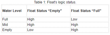
At this point, we have the two signals FULL and EMPTY coming from our tank that will assume states as described in Table 1. When the empty tank condition is verified, the logic will turn on the pump and start the watch dog. If a full tank signal is read within the set time, the pump will be stopped and the watch dog reset; otherwise, the pump will be stopped by the intervention of the watch dog and the Alarm LED will light. The alarm will automatically reset when the tank empty condition is reached.
Schematic Diagram
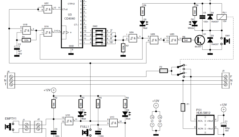
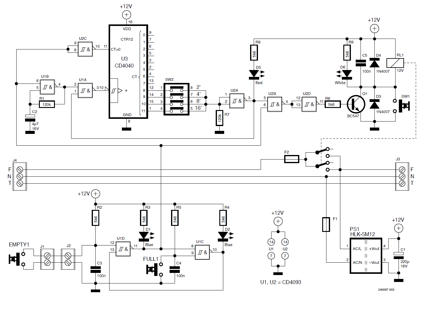
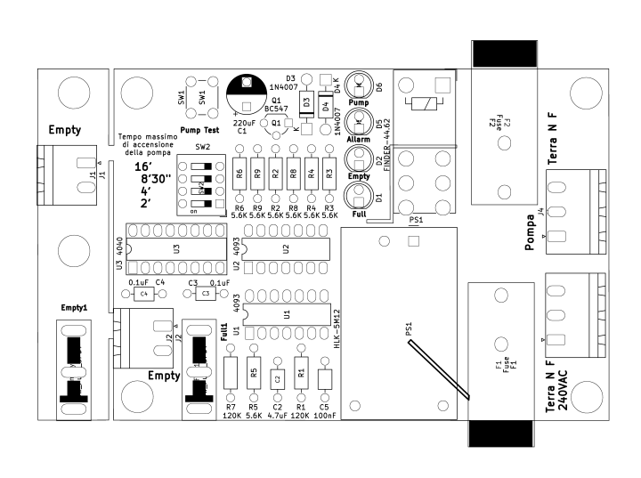
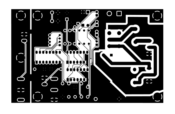
The circuit (Figure 1) consists of five blocks and respectively: power circuit (operating at 240 Vac), 12 VDC power supply, level sensors (floats), input memory, pump control, watch dog. The power circuit includes the 240 Vac input terminal block, pump protection fuse and 12 VDC power supply protection fuse, relay contact part, and pump connection terminal block.
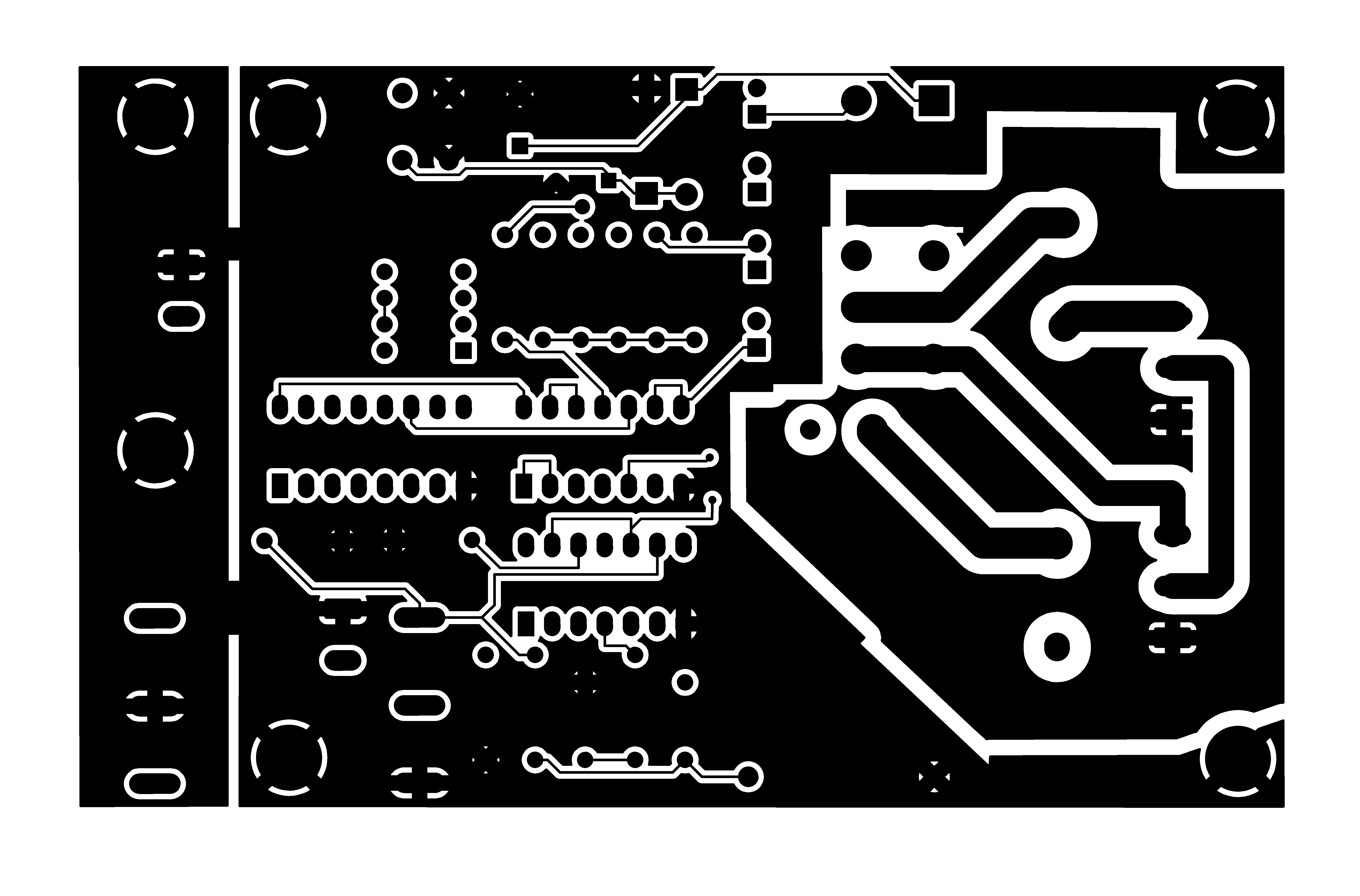
The tracks related to the connections between the terminal blocks and the relay contacts are all double (upper face and lower face) to enable them to withstand high currents. The 12 VDC power supply is sealed so that we can be sure that we have met the prerequisites for double insulation certification and the minimum requirements for the power supply part of this class of equipment.
Our power supply is capable of delivering 5 W, so we could draw a maximum current of 450 mA at the output without time limitation. The output is protected against overload. Concerning the heath dissipation by the power supply, no action is necessary because the module is self-dissipating through its walls. A 220 µF capacitor was inserted to ensure good leveling of the 12 VDC. The level sensors are made with two micro switches, one of which is installed on the main PCB while the other is mounted on a small PCB and connected to the main board by two terminal blocks and a couple of wires (the connection is not polarized). The two micro switches are to be connected to two floats using a thin cord. To avoid premature wear or breakage, the lanyard should be made of material resistant to water, moisture and attack by any mold or mildew; in our implementations, we opted for 1 mm polyester cord normally used in boating.
The floats must be of sufficient weight to trigger the micro switches but not such as to damage their movement; we used hard plastic floats with a diameter of 80 mm equipped with threads both in the upper part, where we secured the lanyard, and in the lower part where we placed a bolt with 3 stainless-steel nuts to slightly increase the mass of the float and ensure smooth operation of the system.
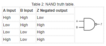
The input memory consists of a bistable flip-flop (U1D and U1C) which directly receives the signal from the micro switches connected to the two floats. The inputs are referenced to +12 V through two 5.6 kΩ pull-up resistors, while two 100 nF capacitors are acting as noise suppressors to ground. The NAND logics are priority sensitive to the logic level Low, as can be seen in Table 2.
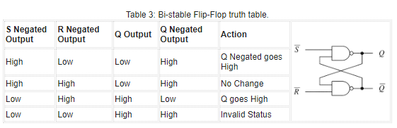
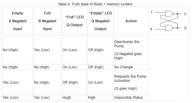
This causes the state change of our flip-flop to occur according to Table 3. If at this point we connect to the negated-S input the Empty float and to the negated-R input the Full float and to the negated-Q output the LED signaling the tank-full status (Full LED) while to the negated-Q output the LED signaling the tank-empty status (Empty LED) we will have what is shown in Table 4.
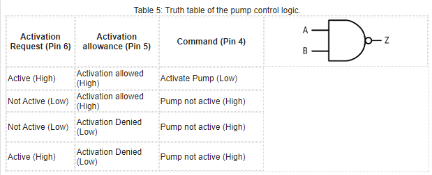
The pump control is realized with NAND (U2B) which receives the turn-on request from the memory (pin 6) and compares it with the turn-on clearance coming from the watchdog (pin 5). The truth table for this circuit is shown in Table 5.
The output signal from the NAND is inverted and used to control the transistor that activates the pump turn-on relay. A pushbutton (SW1) has been placed in parallel with the transistor that controls the relay coil; if pressed, it causes the activation of the relay, bypassing all circuitry and logic. This choice ensures to verify the correct operation of the power part of the pump and the low-voltage power supply. In this condition, the PUMP LED should lit.
As anticipated, the control unit provides protection on the maximum running time of the pump (watchdog). This protection is made with a clock generator (U1B), a counter (U3), the protection time selector (SW2), and a handful of control logic all handled by the pump turn-on request signal generated by the memory.
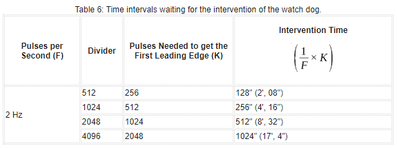
When the memory requests to turn on the pump, it simultaneously unlocks the watch dog counter (U3) via U2C and starts the clock generator (U1B pin 6). In this mode, the counter starts. U3 is a 12-stage binary counter, i.e., a device that can divide a clock by 2 up to 4096 according to the exponent of 2. We omit the first outputs, as they are too fast for our purposes, and consider only the last 4 (divided by 512, 1.024, 2.048, 4.096).
To stop the pump the positive edge is used, that is, the one that the counter generates when it reaches half the pulses needed to complete the cycle by that division factor, so we will have that the pulses needed to stop the pump will be 256, 512, 1.024, 2.048. Starting from a clock of about 2 Hz, the watch dog tripping times shown in Table 6 will be obtained.
Selector switch SW2 connects one of the four outputs to NAND U2A, which inverts the output of the counter so that there is a High level before the watch dog tripping and a Low level at the time when the wait time has expired. The input of U2A is connected to a pull-down that ensures a low level in case you choose to turn off the watch dog (the four switches of SW2 all to Off).
In addition to controlling the pump turn-on circuit, the output of U2A turns on the Alarm LED, indicating that a pump lockout has occurred due to the watch dog tripping. The output of U2A, going Low, forces High the output of U2B, causing the relay to open (pump stopped) and simultaneously stops the clock signal (U1A). This prevents the counter from advancing and changing state with time. The whole watch dog chain returns to the initial state at the time when the low reservoir level signal comes up again.
If you need different watch dog response times than those currently available, it will be possible to modify the clock to obtain the times useful for your installation. The new clock is calculated using the formula:
tClock = t/1024
Where t is the wait time expressed in seconds and tClock is the period of the clock. Once you get the period of the new clock, you calculate the new value of R1 with the following formula:
R1 = (tClock/0.7767840746)/0.0000047
The calculated value should be replaced with the nearest commercial value (e.g., 136 kΩ with 120 kΩ), and component tolerances should also be considered in the verification, which, especially for capacitors, very often can be as much as ±20%. The calculated value will correspond to switch 3 of selector SW2, i.e., the current 512"; in this way you will have a range of new timings ranging from a quarter of t to double t.
Power Relay and Maximum Load Current
The load is controlled by a Finder 44.62 series relay. These relays can have double or single contacts but, in any case, the maximum current they can handle is 16 A with resistive loads. Since the pump is an inductive load, this current must be reduced according to the angle of phase shift between current and voltage (cosφ). Each pump has its own characteristic cosφ which can also vary according to load conditions so, as a precaution, we consider a cosφ = 0.6 and — consulting the tables provided by Finder — we derive a correction constant for the maximum manageable current of 0.8. Multiplying the rated current by this factor, we get 16 × 0.8 = 12.8 A.
To further increase the safety margin, we can set a maximum threshold of 10 A, except for specific and unusual conditions. If it becomes necessary to control pumps that draw a current greater than 10 A or that cause sparking on the relay contacts or that operate on three-phase power three-phase power supply, it is possible to connect to our control unit a suitable contactor of adequate power for our needs, with an excitation coil operating at 230 Vac. In this way, this contactor will represent the load of the control unit, while the actual, higher load current of the pump will be switched by the high-rate contacts of the contactor.
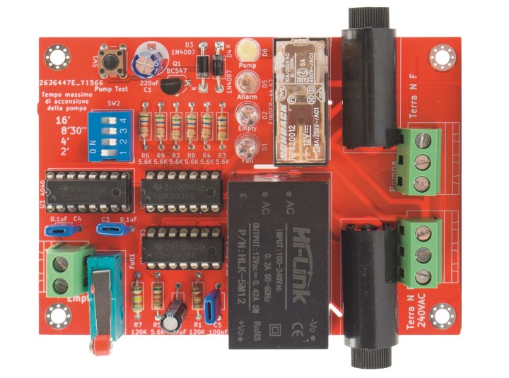
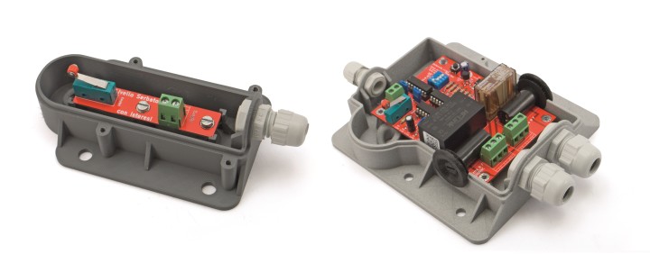
Practical Realization
As far as the construction is concerned, the only weak point might come from a messy assembly that could somehow create critical conditions between the tracks connected to the mains voltage and the ground or other circuit parts, so all that is needed is to make burr-free soldering and, at the end, possibly eliminate flux residues with a good wash in isopropyl alcohol (printed circuit board cleaning cans are fine) with a nail brush, and you are done.
For heat dissipation, since there are no components that heat, no precautions need to be taken so, resistors, diodes, electrolytic capacitor, power supply module can be mounted in contact with the PCB. As for fuse holders, terminal blocks, and micro-switches, mounting them tightly against the PCB increases their resistance to mechanical stress during use. As for mounting six components, solder the low components first and then the higher ones as you go: this will enable you to proceed more quickly with assembly.
Positioning the Floats
As already mentioned, the floats are connected to the micro-switches by a thin string, whose length is a function of the size of the tank and the level change we intend for the water to make between the pump's tripping point and the maximum level. In choosing the location where we place our floats, we must make sure that there is no possibility of the cords getting twisted. In making this assessment, we must also consider the way the water enters the tank since it may happen that the lanyards or floats are affected by the flow of water or the turbulence it creates in entering the tank, altering their operation. To facilitate positioning, we mounted one micro-switch on the main plate and the other on a small PCB that allows for easy, different repositioning if problems are encountered.
Wiring
Our baseplate needs three wires, one for the remote float, one for the power supply, and one going to the pump. The wire connecting the remote float is a two-conductor and has no cross-sectional problem; considering that it works at 12 V and carries 0.002 A, any solution with two insulated wires will be suitable. The power supply cable will have to be three conductors one (live, neutral, ground) with a cross-section of at least 1.5 mm2, to withstand the pump current which, as previously said, should not exceed 10 A. The same will apply for the cable feeding the pump. Please note that in installations operating at 230 Vac, conductors with a diameter of less than 1.5 mm2 are not allowed.
Calibration
Once the assembly, positioning of the floats and wiring are completed, we can proceed to the calibration of our device. The first step will be to adjust the length of the cords that support the floats. Having arranged the floats, we will proceed as follows:
- All switches of selector switch SW2 should be set to Off. This causes the watch dog to be excluded.
- Let the water level drop until the empty tank float trips (the EMPTY LED lights up and the relay commands the pump to turn on)
- Measure the filling time, i.e., the time for which the controller keeps the pump running.
- Choose the switch on switch SW2 that corresponds to the time immediately above the fill time and set it to ON.
- In case the filling time is longer than 17 minutes, it will be necessary to adjust the clock.
Tank Level Control
This design represents a solution in the field of water automation that optimizes energy use and minimizes wear and tear on pumps, while providing a practical and reliable solution for areas without aqueduct connections or in which the water supply is not constant. The simplicity of implementation, combined with the efficiency and reliability of the system, makes this solution particularly attractive for sustainable water resource management.
Component List
Resistors
R1, R7 = 120 kΩ
R2…R6, R8, R9 = 5.6 kΩ
Capacitors
C1 = 220 μF, 16 VL, electrolytic
C2 = 4.7 μF, 16 VL, electrolytic
C3…C5 = 100 nF, ceramic
Semiconductors
D1, D2 = LED 5 mm, Blue
D3, D4 = 1N4007
D5 = LED 5 mm, Red
D6 = LED 5 mm, White
Q1 = BC547 transistor
U1, U2 = CD4093
U3 = CD4040
Miscellaneous
SW1 = Microswitch
SW2 = 4-ways Dip-Switch
RL1 = 12V Relay (Finder 44.62)
Empty1, Full1 = Lever microswitches (1 each)
PS1 = 12V Supply Module HLK-5M12
2× 7+7 pin DIL socket
1× 8+8 pin DIL socket
2× Fuse holder, PCB type
2× 2 Poles screw terminal, pitch 5.08 mm
2× 3 Poles screw terminal, pitch 5.08 mm
PCB S1715 (100×71 mm)
About the Author
Currently retired, Leonardo Sammartano teaches applied electronics and digital fabrication to high school students. He started in the 1970s as a designer in Olivetti's Special Instruments Department and continued in Marconi and other industries in the field. He later moved to the nuclear industry and then became interested in risk management systems in manufacturing areas and large construction sites, also in the energy sector.


Discussion (0 commentaire(s))