
AudioVideoStations - remote controlled wireless Loudspeakers
Wireless independently powered devices are "the future", so why not using the same approach for loudspeakers, level meters, and other audio (and video) equipment? No cabling, easy transport and a lot of comfort. This project is in an early stage, but it already gave some daughter projects and spin-offs a birth. More to come!
My friends and me like DJing and doing DJ videos not only in the studio, but during the lovely Cologne summer also out there in the "field". Well, there are legal and not so legal options, for example in public parks, but that is another story. In any case, you have to think about a sufficient power source, and you have always a lot of effort to transport, mount and demount the equipment.
Electric generators were never an option for me, they are stinking and loud and especially the cheaper ones are not reliable enough. So we started with 12 V lead batteries and 1 inverter for the whole system, but cabling and the transport of 24-kg-batteries always sucked. Soon, we discovered the option to use RF transmission to transmit the Audio from the DJ equipment to the loudspeakers. The delay was so low that we even could receive left and right channel with separate receivers directly at the L and R speaker each, without loosing the stereo effect. The idea of independently powered, wireless, mono loudspeaker stations was born, and later we even extended it to a satellite/subwoofer system of even 4 independent stations. Believe me, it is very comfortable when you can grab a loudspeaker-battery-bundle and put it at the place where you like to have it, without thinking on any cables. You even can do that while the loudspeaker is playing music!
First, we used smaller 12-V-batteries and small inverters for active 230-V-powered loudspeakers, but in principle it is complete nonsense to first get from 12 V DC to 230 V AC and then back again to DC for the amplifier inside the speaker. I quickly then came to small mono amplifiers offered in the internet, which can be powered with 12 V, 24 V or higher, and passive boxes instead of active ones. You can get very good (and loud) ones used in the internet, for a quite low price. The sound is in any case better than the one from an active PA box - at least a PA box for a reasonable price.
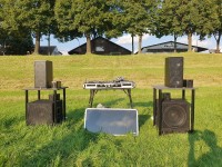
To get DJ equipment independent, you can use simple power banks for smartphones and laptops and small boost converters (the mixer and the digital jog wheel equipped players consume not more than 5 to 8 Watts; In fact, it turned out that we get the best results if we power each device with its own power bank). But for the amplifiers, if you really want some "pressing" volume in an open air area, you have to work with higher DC voltages. We are now at 36 V and 10.5 Ah bicycle batteries, which gives us enough energy for 10 hours music and beyond. The main image is showing a system of 4 independent stations, the batteries, amplifiers and audio receivers are located in the small black boxes (in the meantime, I bought more powerful 15 inch subwoofers.)
However, it is not comfortable to always walk to all loudspeakers and subwoofers and configure the volume at each of the stations separately. That is why my friend Marco and me considered a remote control for the volume of the loudspeaker stations, and so we came to this project.
Our first goal was to get the volume control of our mini mono amplifiers (https://doukaudio.com/products/nobsound-g2-pro-hifi-subwoofer-full-frequency-mono-digital-power-amplifier-300w) accessible. Inside these mini class D amplifiers, we found a logarithmic 50 k potentiometer as volume control, and it turned out that the music signal is going through it, which makes a digipot (our first idea) not applicable. We then came to the good old Alps motorized potis; they have its price (around 20 Euros, if you are lucky), but are very reliable and the most proper and "pure" solution. We are currently using RK27112MC stereo potentiometers, and as we just have to control mono, this gives us the option to use the second channel as feedback about the level of the potentiometer.
I will soon switch our GitHub project to public. But here already some facts about our first prototype of "loudspeaker station" electronics. For remote control we are using Wifi, the power of 1...2 Watt needed is in my eyes not a big deal regarding the total power consumed of about 20...50 Watts for one of the loudspeaker stations. Our choice of an ESP32 as controller was obvious, as there are many cheap boards and a rich ecosystem of Arduino libraries. As transport "language" we are using MQTT, and I discovered there is a library to even establish an MQTT broker on an ESP32. (In fact, we are currently developing a touch display based "controller station", which is basically a 5 inch ESP32 display by Elecrow plus a power bank, and the MQTT broker as well as the control logic runs reliably on that ESP32.)
As controller board for each of the loudspeaker stations, we soon switched from a ESP32 Wroom based dev board to a XIAO ESP32 module, and we are using a very compact Grove connector extension board for it. For motor control of the Alps potentiometer we are using a ready-made "Grove Mini Motor" module. To measure the potentiometer level, we are using an extern ADS1015 with 12 bits (it turned out that the built-in ADC of the ESP32 was hardly usable, especially for small voltages). Both the Motor driver board as well as the ADS1015 are connected via I2C-Grove-cables to the XIAO ESP32 (see the module diagram image below about this main part of the electronics, the modules and its wiring). As there were no cheap target boards for the ADS1015 breakout board we bought available, we designed our own, which can carry the breakout board and also similar, pin-compatible ones (see image ADC PCB). We also designed a PCB for the Alps motorized potentiometer, which is currently in production.
A Grove LED bar for visual feedback of connection state and received message, a Grove DIP switch (for configuring a station "address") and a power module to get 5 V for the ESP32 from 36 V are completing the electronics. All this is housed in a cheap plastic housing (the electronics box). Below you can see 2 prototypes of this electronics box. As we did not have the Motor Pot PCB and the ADC PCB that time, we just soldered wires to the Alps Potentiometer. To connect the ADC BoB, we used a general prototyping PCB with female headers and screwclamps.
We are also working on an outer housing which keeps the inner electronics box, the amplifier, the Audio wireless receiver, the bicycle battery and a power switch together. A Speak-on-connector by Neutrik for the loudspeaker is in fact the only connection to the outside! You can see a first mockup for this outer housing in the image below. As housings, especially bigger ones, are really expensive, I can strongly recommend to use simple plastic boxes to test everything and get a feeling for the space needed. The one depicted is a 5 Euro piece from the local "Baumarkt".
We made first test successfully and it is really thrilling how easy everything is going. Put your loudspeaker on a stand, place the station box besides it, plug the cable from the loudspeakers in, press the power button, activate the wireless receiver in the box - and let the music play.
Electric generators were never an option for me, they are stinking and loud and especially the cheaper ones are not reliable enough. So we started with 12 V lead batteries and 1 inverter for the whole system, but cabling and the transport of 24-kg-batteries always sucked. Soon, we discovered the option to use RF transmission to transmit the Audio from the DJ equipment to the loudspeakers. The delay was so low that we even could receive left and right channel with separate receivers directly at the L and R speaker each, without loosing the stereo effect. The idea of independently powered, wireless, mono loudspeaker stations was born, and later we even extended it to a satellite/subwoofer system of even 4 independent stations. Believe me, it is very comfortable when you can grab a loudspeaker-battery-bundle and put it at the place where you like to have it, without thinking on any cables. You even can do that while the loudspeaker is playing music!
First, we used smaller 12-V-batteries and small inverters for active 230-V-powered loudspeakers, but in principle it is complete nonsense to first get from 12 V DC to 230 V AC and then back again to DC for the amplifier inside the speaker. I quickly then came to small mono amplifiers offered in the internet, which can be powered with 12 V, 24 V or higher, and passive boxes instead of active ones. You can get very good (and loud) ones used in the internet, for a quite low price. The sound is in any case better than the one from an active PA box - at least a PA box for a reasonable price.
To get DJ equipment independent, you can use simple power banks for smartphones and laptops and small boost converters (the mixer and the digital jog wheel equipped players consume not more than 5 to 8 Watts; In fact, it turned out that we get the best results if we power each device with its own power bank). But for the amplifiers, if you really want some "pressing" volume in an open air area, you have to work with higher DC voltages. We are now at 36 V and 10.5 Ah bicycle batteries, which gives us enough energy for 10 hours music and beyond. The main image is showing a system of 4 independent stations, the batteries, amplifiers and audio receivers are located in the small black boxes (in the meantime, I bought more powerful 15 inch subwoofers.)
However, it is not comfortable to always walk to all loudspeakers and subwoofers and configure the volume at each of the stations separately. That is why my friend Marco and me considered a remote control for the volume of the loudspeaker stations, and so we came to this project.
Our first goal was to get the volume control of our mini mono amplifiers (https://doukaudio.com/products/nobsound-g2-pro-hifi-subwoofer-full-frequency-mono-digital-power-amplifier-300w) accessible. Inside these mini class D amplifiers, we found a logarithmic 50 k potentiometer as volume control, and it turned out that the music signal is going through it, which makes a digipot (our first idea) not applicable. We then came to the good old Alps motorized potis; they have its price (around 20 Euros, if you are lucky), but are very reliable and the most proper and "pure" solution. We are currently using RK27112MC stereo potentiometers, and as we just have to control mono, this gives us the option to use the second channel as feedback about the level of the potentiometer.
I will soon switch our GitHub project to public. But here already some facts about our first prototype of "loudspeaker station" electronics. For remote control we are using Wifi, the power of 1...2 Watt needed is in my eyes not a big deal regarding the total power consumed of about 20...50 Watts for one of the loudspeaker stations. Our choice of an ESP32 as controller was obvious, as there are many cheap boards and a rich ecosystem of Arduino libraries. As transport "language" we are using MQTT, and I discovered there is a library to even establish an MQTT broker on an ESP32. (In fact, we are currently developing a touch display based "controller station", which is basically a 5 inch ESP32 display by Elecrow plus a power bank, and the MQTT broker as well as the control logic runs reliably on that ESP32.)
As controller board for each of the loudspeaker stations, we soon switched from a ESP32 Wroom based dev board to a XIAO ESP32 module, and we are using a very compact Grove connector extension board for it. For motor control of the Alps potentiometer we are using a ready-made "Grove Mini Motor" module. To measure the potentiometer level, we are using an extern ADS1015 with 12 bits (it turned out that the built-in ADC of the ESP32 was hardly usable, especially for small voltages). Both the Motor driver board as well as the ADS1015 are connected via I2C-Grove-cables to the XIAO ESP32 (see the module diagram image below about this main part of the electronics, the modules and its wiring). As there were no cheap target boards for the ADS1015 breakout board we bought available, we designed our own, which can carry the breakout board and also similar, pin-compatible ones (see image ADC PCB). We also designed a PCB for the Alps motorized potentiometer, which is currently in production.
A Grove LED bar for visual feedback of connection state and received message, a Grove DIP switch (for configuring a station "address") and a power module to get 5 V for the ESP32 from 36 V are completing the electronics. All this is housed in a cheap plastic housing (the electronics box). Below you can see 2 prototypes of this electronics box. As we did not have the Motor Pot PCB and the ADC PCB that time, we just soldered wires to the Alps Potentiometer. To connect the ADC BoB, we used a general prototyping PCB with female headers and screwclamps.
We are also working on an outer housing which keeps the inner electronics box, the amplifier, the Audio wireless receiver, the bicycle battery and a power switch together. A Speak-on-connector by Neutrik for the loudspeaker is in fact the only connection to the outside! You can see a first mockup for this outer housing in the image below. As housings, especially bigger ones, are really expensive, I can strongly recommend to use simple plastic boxes to test everything and get a feeling for the space needed. The one depicted is a 5 Euro piece from the local "Baumarkt".
We made first test successfully and it is really thrilling how easy everything is going. Put your loudspeaker on a stand, place the station box besides it, plug the cable from the loudspeakers in, press the power button, activate the wireless receiver in the box - and let the music play.
Discussion (1 commentaire(s))