
VibroTactile Gloves against Parkinson's disease

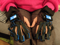
Designed specifically for patients with Parkinson's disease, these gloves utilize vibro-tactile stimulation to effectively combat motor impairments. By targeting the fingertips, these gloves provide targeted relief, revolutionizing the management of motor discomfort associated with Parkinson's. Join me in transforming the lives of those affected by Parkinson's disease.
Watch the Video: VibroTactile Gloves (youtube.com)
Introduction
After a family member was diagnosed with Parkinson's, I embarked on a mission to develop a set of VibroTactile gloves based on the findings of a study by Peter A. Tass (https://www.ncbi.nlm.nih.gov/pmc/articles/PMC8771098/).
It is known that in Parkinson's patients, brain cells exhibit a kind of synchronicity. When certain neurons are activated, such as during actions like walking, adjacent neurons also fire, leading to uncontrolled movements. This synchronization can severely impair motor function, even rendering walking impossible for some patients.
The solution
Research has shown that stimulating these brain areas with a specific pattern can "desynchronize" the neurons, allowing them to operate independently again, vastly improving the patient's motor skills. While some patients may opt for invasive brain implants for this stimulation, the mentioned research indicates that stimulating sensitive fingertips can achieve similar positive effects. Sessions lasting up to 4 hours a day have shown significant improvement, as reported in this NBC news feature: https://www.youtube.com/watch?v=YEEwbxFT4Bc&t=79s.
The gloves emit random pulses via special pads on the fingertips during treatment. These pulses are random for each finger, with a randomized pulse jitter, but synchronization between hands is crucial. Both hands should emit the exactly same random pattern, at the same time in sync.
My design
The hardware used during the research phase requires a bulky external controller with shoulder straps and large wires leading to the hands, impairing the quality of daily-life quite a bit as seen on the NBC video.
The gloves I've developed offer far more significant benefits:
The original aim was to create gloves for my family member to wear during daily activities like walking the dog, or cooking, without the inconvenience of wires and a bulky controller, enabling her to lead a more "normal" life.
I sincerely hope that this project could be of benefit anyone with Parkinson's disease and improve their life. That is the reason I seek publicity for this project.
It aligns with goal 3 of the SDGS: THE 17 GOALS | Sustainable Development (un.org) about Good Health and wellbeing.
@Elektor Staff: I would like to submit this project to the #Elektor2024Contest
Disclaimer: Always consult with a neurologist before implementing this design. I accept no liability for any damage or injury resulting from the use of this design.
So without further ado: Lets dive in!
Inner Working
The theory behind these gloves is that by stimulating the fingertips with small vibrations, these stimuli will reach the brain through the nervous system, inducing desynchronization of ‘sticky’ neurons. Creating vibrations on the fingertips seems simple enough. I used some vibration motors for this purpose: Seeed Studio 316040001 Mini Vibration Motor for Multipurpose | RS (rs-online.com) These motors are basically PCB-Motors, with a little counterweight spinning around creating vibrations. So if you apply voltage, you’ll get vibrations. Easy enough.
At the core
The heart of these gloves are formed by 2 Lilygo T-Display-S3 boards: T-Display-S3 – LILYGO®
These boards provide a nice bright 1.9" diagonal, Full-colour TFT Display with a capacitive touch sensor on top. It's powered by an ESP32 S3, so this gives us plenty processing power and memory to work with.
Of course, no ESP32 comes without Wi-Fi and Bluetooth BLE. This gives us opportunities to connect them to a smartphone, or Wi-Fi.
There is another very important use for the Wi-Fi interface, but more on that later.
One other nice aspect of the Lilygo board is the built-in LiPo battery charger.
Since the design goal was to make these gloves wireless, they should be battery powered.
The charger is capable of using the on-board USB-C connector as a power-source to charge the LiPo, so charging these gloves should be as easy as plugging in your smartphone.
The Build: Fingertips
By now we already have the basic ingredients: microprocessor, touchscreen, USB-charging, LiPo batteries, vibration motors..
What can possibly go wrong? Well.. a Lot
It all starts at the fingertips. In the first design stages, I’ve tried to make the gloves as comfortable as possible. I took some off-the-shelve running-gloves, and started fiddling around with the little motors. The goal was to attach these little motors to the gloves in such a way that they would stay put on the exact same spot of the fingertip.
I cut some holes in the fingers, placed the motors and tried to sew them in place. This did not work. When putting the gloves on, the pressure of the fingers would slide the motor out of place, breaking the little wires.
Next on: Hotglue! Of course you need hotglue. Al least, we thought. So we glued the motors on a piece of Velcro-tape, and wrapped that around the fingers.
This looked like a solution. But unfortunately, the rotational vibration of the motors would eventually still break the little wires coming off the motors.
So, what the heck?! Are we stuck with motors that eventually break themselves? Every time we tried these gloves, one of the motors broke down. The best one lasted merely half an hour.
Back to the drawing board. I needed a way to fixate these little fragile wires of the motor.
That’s when I started to create custom 3D printed fingerpads.
This solved basically 3 problems at once:
1- By designing a slight cavity in the fingerpads, and embedded the motors flush with the cavity, the wearing comfort increases a lot.
2- The wires of the motors are now fully protected, because they run in tunnels inside of the pad, connecting to the larger silicone break-out wires. Within the pad, there is a space where these wires are soldered together. This space is later filled-up with glue. This design fully embeds the motor including its tiny wires in glue, becoming a single solid piece. No vibration could lead to broken wires anymore.
3- To adjust the pad to the thickness of the patient’s finger, we could now use Velcro-tape wrapped around specially designed ‘handles’ of the pad. These are nice mounting points for the various parts of the fingers.
The Build: Batteries
The Gloves itself are just off-the-shelve running-gloves. Not really thick, and comfortable to wear.
By cutting off the fingertips of the gloves, we keep the hand-part.
Because the batteries need to go somewhere, I opted for a design whereby the controller is placed on the back of the hand, and the battery is placed on the wrist.
This leaves room for two 18650 LiPo cells in parallel. I opted for cells placed in a battery holder instead of a LiPo pouch somewhere hidden, so you could replace the cells with freshly charged ones, should you come into a situation where you cannot charge the gloves.
The holder with batteries is ‘folded’ into the sleeve of the glove, to prevent any sharp edges of the battery holder. You can also use a single 18650 cell. This will halve the weight of the battery and feels less bulky.
The total run-time of the gloves will depend on the capacity of the cells. When using large capacity cells, the gloves would run for 16 hours straight on 1 cell per glove, giving 4 days of maximum use (4 hours per day). Using 2 of those cells per glove, this will roughly double to 8 days.
The battery is connected by a JST connector to the controller on the back of the hand, so you can disconnect the battery completely when the gloves are stored for a longer time. This will prevent the controller from slowly draining the batteries to death. The charge-controller of the Lilygo will not prevent that. I recommend you use protected batteries: Blog - Types of 18650 battery | NKON.
Be aware that you wear these batteries close to your body, and protected batteries will also protect against overheating.
The Build: Controller
As mentioned, the Lilygo T-Display-S3 Display with touchscreen forms the basis. This display has various connector pins underneath.
I have created a tiny PCB that slides over these pins, thus creating a sandwich. This PCB contains the JST connectors for the battery, the motors on the fingertips and some buffering circuitry.
Nothing really special on this board. If you look at the schematics, you will first find some capacitors (C1 and C2). Because we are pulsing motors, we generate a lot of noise on the supply lines. Especially when the batteries are low in charge. C2 is filtering higher frequencies, while C1 is used to smooth out the inrush currents when a motor is activated. This should help to stabilize the voltage on the controller itself. Although the Lilygo has a small capacitor next to the processor itself to stabilize it’s supply, it’s good practice to decouple these parts of the circuit.
Next up is the buffering of the output signals to the motors. It would be a very bad idea to power the motors right off the processor’s output pins (if even possible given the current). So we need to delegate that task to some external MOSFETs. Q1 trough Q4 are 2N7000 MOSFETS, which have a handy built-in diode to short the back-EMF coming from the motors. Back-EMF is generated when a motor is disconnected from it’s power supply. The existing magnetic field around the coils suddenly collapses, generating a voltage opposite to the supply voltage. This negative voltage could potentially destroy the pins of the microcontroller, so this diode is crucial in shorting this negative voltage to safe levels.
A 100K pull-down resistor was added from the gate to ground. This resistor will pull the gate of the MOSFET low, ensuring that no motors unexpectedly activate by themselves when the microcontroller is not actively driving them.
This is no precaution. It’s a necessity. During boot-up of the processor, most of it’s pins are in a high impedance state, leaving the gate of the MOSFETS floating around, randomly activating motors.
Also, when the gloves are not actively used, the processor is put in a low-power state. This state disables most of the hardware in the processor, thus also stops driving it’s pins high or low. A simple resistor will give us a fixed off state, when no pins are active.
The value of 100K seems very large, but it’s chosen to form a balance between battery consumption, and pull-down functionality.
Because every time you add a pull-down resistor, you will have to work against it to pull it up when needed, creating a larger current draw.
The rest of the board is used to break out all the JST connectors to the right places.
I could have used SMD components, but it won’t make the sandwich of the two boards any thinner because of the height needed for the JST connectors to the fingers. So I opted for trough-holes instead. It makes the build a little bit more fun, and gives a bit more ‘body’ to the PCB. Oh well, do as you like. PCB designs are attached anyway.
I ordered a stack of 10 of these PCB’s at PCBWay. It all went smooth and they looked great.
Since we are switching DC-loads here, it’s a good idea to twist the wires running from the controller-board to the motors. Twisting these wires will prevent a lot of noise being radiated from these wires. You can maybe even use some small ferrite-beads on top of that.
The Build: Software
Voila! Le pièce de resistance!
I am a software developer at heart, so when I finally got to this part, I really got my cake.
The main design goal was: No bulky wires. This means that you have 2 gloves, containing both exactly the same hardware. According to the study of Peter A. Tass, we need the gloves to give the following pulses:
“Sequences of vibratory stimuli (with 250 Hz vibration frequency and 100-ms duration) were delivered at a rate of 1.5 Hz, corresponding to a 667ms cycle (Tass, 2017; Syrkin-Nikolau et al., 2018; Pfeifer et al., 2021). During a sequence, each fingertip of fingers 1–4 was stimulated exactly once, where both hands were stimulated in a mirrored manner. Sequence order was randomly varied. Inter-stimulus intervals were constant (for regular vCR) or subject to moderate jitter (for noisy vCR)”
Okay.. so basically we have cycles of 667 milliseconds, in which the 4 fingers (thumb doesn’t count) need a vibration of 100 milliseconds.
That leaves us with 667-(4x100)=267ms of ‘space in between’. This space is not evenly distributed, but is varied to form jitter. This Jitter is then randomly applied to each sequence. And on top of that, the order of which finger is activated if also randomly chosen per sequence. But, both hands are perfectly mirrored. To top it off, we needed to use PWM to also vary the intensity of the motors.
This is a problem in itself. It means that the gloves have a lot of random behaviour, but they both need to know what they are doing. This is near-impossible without a form of communication between the gloves.
At first, I wanted to connect both Gloves to a smartphone app using Bluetooth BLE. This app would generate all needed sequences for a session upfront, send it to the gloves, and press the ‘play’ button simultaneously.
Problem is that it takes a lot of memory to store thousands of sequences for a session of 4 hours, and they will eventually loose sync because of drift.
So eventually I opted for a direct connection. Looking at the options (Bluetooth, Wi-Fi) I settled on ESP-Now. ESP-Now is a custom wireless communication protocol developed by Expressif: ESP-NOW Wireless Communication Protocol | Espressif Systems and is supported on most of their controllers.
This protocol looks like Wi-Fi, and uses the same hardware, but much more simpler and deterministic. And even better, it doesn’t need a Wi-Fi access-point! Communication is purely based on MAC-addresses.
Allright. We can communicate now!
When the gloves are running, every sequence they need to ‘play’ on the motors is calculated up-front and send-over to the other glove in a primary/secondary fashion.
Both gloves are playing their sequence, and during that time, the primary glove calculates and sends over the next sequence just-in-time to the secondary glove, together with a precise start-time.
When the current sequence is completed, both gloves know the next sequence, and it’s exact start-time. They both wait for it, and simultaneously start playing the new sequence while calculating the next sequence thereafter.
This is how the gloves are playing random sequences, but still mirror each other.
The secondary glove is also calculating new sequences itself, but won’t use them unless it doesn’t receive the new sequence to play from the primary glove in time. This could happen when communication on the 2.4 GHz band is disrupted by say a microwave or something.
Remember that you can walk around your kitchen while using these gloves, so this is a reality. After disruption, both gloves will be in sync again within 700ms.
So how do the gloves compare a sequence start-time to a trusty timesource?
Well, I have looked at connecting an RTC, or a crystal to the controller to create a permanent time-source. But it would increase the component-count and won’t fit. This could however be done when choosing SMD components instead of trough-holes.
Instead, I opted for semi-time. The gloves don’t need to know the exact time, the only thing they need to agree on is ‘a’ time, like.. the amount of microseconds since power-up.
This value is communicated every second from the primary to the secondary, whereby the round-trip time (RTT) is measured between the gloves. The secondary glove receives the time-message, and ads half of the RTT to this time to set it’s own clock.
After a lot of tweaking and tuning this method, which is a variant of the NTP-Protocol, synchronizes the internal clocks of the gloves within a range of 320uS!
With less then a third of a millisecond precision, this is enough for our goal.
Most of our roadblocks are out-of-the way now.
So whats left is the user interface.
I won’t go into much detail about the fact that I needed to write a new display driver and a new touchscreen driver, but it all boils down to the fact that documentation is very scarce here. Yes there are coding examples, but they are mediocre at best, or use outdated framework versions.
For the user-interface, I thought I deserved a little mental vacation after weeks of low-level C++ bit-shifting and byte counting. I wanted something easier, so I opted for LVGL (LVGL - Light and Versatile Embedded Graphics Library). LVGL is an embedded graphics library with all bells-and-whistles you need for creating touch user interfaces.
To make my life even more easier, I treated myself with Squareline Studio (SquareLine Studio - Design and build UIs with ease) to have a WYSIWYG editor, which generates the UI code for you.
With these tools, creating the ‘software application’ itself was more like creating desktop software. Abstract all the technical stuff away, create user-stories for the UI, and implement them like you would on any application.
This means implementing various menus, buttons, screens and settings. And of course, these settings sync between the gloves using the communication-channel created earlier with ESP-Now.
This leaves Bluetooth BLE unused, ready to connect the Gloves to your smartphone!
I started the basic App for this, but haven’t implemented a lot of functions yet since at the time I didn’t even knew if the Gloves even worked or not! Yeah, the project-vibe got me.. I know
The Build: Battery Powered
This was my first project where I used batteries to power the ESP32. The ESP32 can be really power-hungry, but I needed something less thirsty..
During the time the gloves are not used, I don’t want to deplete my batteries! So I need a deep-sleep mode.
It started with the obvious:
- Turn off the backlight.
- Turn off the display controller.
- Set the touch-screen chip to a lower power mode.
- Put the processor into sleep.
Luckily, looking at the schematics for the Lilygo controller, I discovered that they have really gone quite far in optimizing the design for low leakage current.
They don’t use much pull-up/pull downs and if they use them, they have very large values like 100KOhm. Even the circuitry for detecting battery voltage, which uses a resistor voltage divider, is tied to an IO-pin at the top, so you can ‘disconnect’ the top resistor of the voltage divider to minimize leakage trough that resistor-divider. Quite clever!
The ESP32 lets you power-down a lot of so called ’power-domains’: discrete hardware parts of the chip. This further reduces power. It even features a special ‘ultra-low-power (ULP) co-processor’ which you can use to turn of the normal processor completely, including it’s memory and all it’s hardware, while still listen for ‘events’ on certain IO-pins.
With these tricks, I brought the current consumption during deep-sleep down to a lousy 390uA.
This is so low, that it would take years for the batteries to drain in this mode.
And yet, a simple press on one of the buttons triggers the controller to wake up, and start the Gloves. Perfect for what we want. The gloves are constantly monitoring the battery voltage. Should it fall below a certain threshold, the batteries are considered empty, and the controller will shut-down everything possible.
Recharge the battery by plugging in the USB-C cable.
Usage:
The Gloves are pretty self-explanatory.
Just put them on, and press the big play button, or pressing the top hardware button.
You can swipe left or right to cycle trough the user-interface, which will give you information about the current session, time left, previous sessions, battery level, connectivity between gloves and different presets and settings you could use.
The backlight will turn off automatically after 30 seconds to save battery life. Even when the gloves are running. A simple tap on the screen will wake the backlight up.
After the session-time, the gloves will stop automatically, depending on the preset.
The gloves will go to deep-sleep automatically after 5 minutes of inactivity (so no running, no pressing buttons). You can also force this sleep by pressing and holding the bottom hardware button.
The gloves will ‘turn-off’.
Only a press on the bottom hardware button will wake it up again.
Icons on the screen will give you the battery level. When it’s time to charge, just plug in any USB-C charger on the side of the controller. The glove will automatically stop charging when full.
If the controller detects that the battery voltage is too low, it will automatically shut down to the deepest sleep mode possible, to prevent draining the batteries.The gloves are operational while charging, so you could use and charge them while reading a book for instance.
This USB-C port is also used to upload new firmware.
Conclusion
All-in-all it was quite a journey! But I loved every step of the way.
Since these gloves are based on early research, its not my right to claim if they work or not, nor if they are actually safe to use. Therefore, use these gloves at your own risk and always consult with your neurologist. Never start or stop any form of medication without consulting your physician or neurologist.
It would be great if the research of Peter A. Tass would eventually increase the quality-of-life of many suffering from Parkinson’s disease.
I am grateful that I could play my minor role in trying to help my relative who was diagnosed with Parkinson’s. At least it was ‘something I could do’, instead of watching a terrible disease doing it’s damage..
For a better world!
Hans van Essen
Introduction
After a family member was diagnosed with Parkinson's, I embarked on a mission to develop a set of VibroTactile gloves based on the findings of a study by Peter A. Tass (https://www.ncbi.nlm.nih.gov/pmc/articles/PMC8771098/).
It is known that in Parkinson's patients, brain cells exhibit a kind of synchronicity. When certain neurons are activated, such as during actions like walking, adjacent neurons also fire, leading to uncontrolled movements. This synchronization can severely impair motor function, even rendering walking impossible for some patients.
The solution
Research has shown that stimulating these brain areas with a specific pattern can "desynchronize" the neurons, allowing them to operate independently again, vastly improving the patient's motor skills. While some patients may opt for invasive brain implants for this stimulation, the mentioned research indicates that stimulating sensitive fingertips can achieve similar positive effects. Sessions lasting up to 4 hours a day have shown significant improvement, as reported in this NBC news feature: https://www.youtube.com/watch?v=YEEwbxFT4Bc&t=79s.
The gloves emit random pulses via special pads on the fingertips during treatment. These pulses are random for each finger, with a randomized pulse jitter, but synchronization between hands is crucial. Both hands should emit the exactly same random pattern, at the same time in sync.
My design
The hardware used during the research phase requires a bulky external controller with shoulder straps and large wires leading to the hands, impairing the quality of daily-life quite a bit as seen on the NBC video.
The gloves I've developed offer far more significant benefits:
- They are wireless. Wrist-mounted batteries providing at least 4 days of use between charges via USB-C.
- A touchscreen on the back of the hand controls all functions. Start/stop, settings and insights in usage.
- Synchronization is ensured as stimulation is random but mirrored between hands. The gloves maintain synchronization within 320uS using the ESP-Now and an adapted version of the NTP Protocol.
- They feature Bluetooth BLE support, allowing users to monitor settings, battery levels, and sessions via a smartphone app.
This project brought together various disciplines, including CAD design, 3D printing, circuit design, PCB design, powered by an ESP32-board, and extensive C++ firmware development for the ESP, including display drivers (and even Home Assistant integration).
The original aim was to create gloves for my family member to wear during daily activities like walking the dog, or cooking, without the inconvenience of wires and a bulky controller, enabling her to lead a more "normal" life.
I sincerely hope that this project could be of benefit anyone with Parkinson's disease and improve their life. That is the reason I seek publicity for this project.
It aligns with goal 3 of the SDGS: THE 17 GOALS | Sustainable Development (un.org) about Good Health and wellbeing.
@Elektor Staff: I would like to submit this project to the #Elektor2024Contest
Disclaimer: Always consult with a neurologist before implementing this design. I accept no liability for any damage or injury resulting from the use of this design.
So without further ado: Lets dive in!
Inner Working
The theory behind these gloves is that by stimulating the fingertips with small vibrations, these stimuli will reach the brain through the nervous system, inducing desynchronization of ‘sticky’ neurons. Creating vibrations on the fingertips seems simple enough. I used some vibration motors for this purpose: Seeed Studio 316040001 Mini Vibration Motor for Multipurpose | RS (rs-online.com) These motors are basically PCB-Motors, with a little counterweight spinning around creating vibrations. So if you apply voltage, you’ll get vibrations. Easy enough.
At the core
The heart of these gloves are formed by 2 Lilygo T-Display-S3 boards: T-Display-S3 – LILYGO®
These boards provide a nice bright 1.9" diagonal, Full-colour TFT Display with a capacitive touch sensor on top. It's powered by an ESP32 S3, so this gives us plenty processing power and memory to work with.
Of course, no ESP32 comes without Wi-Fi and Bluetooth BLE. This gives us opportunities to connect them to a smartphone, or Wi-Fi.
There is another very important use for the Wi-Fi interface, but more on that later.
One other nice aspect of the Lilygo board is the built-in LiPo battery charger.
Since the design goal was to make these gloves wireless, they should be battery powered.
The charger is capable of using the on-board USB-C connector as a power-source to charge the LiPo, so charging these gloves should be as easy as plugging in your smartphone.
The Build: Fingertips
By now we already have the basic ingredients: microprocessor, touchscreen, USB-charging, LiPo batteries, vibration motors..
What can possibly go wrong? Well.. a Lot
It all starts at the fingertips. In the first design stages, I’ve tried to make the gloves as comfortable as possible. I took some off-the-shelve running-gloves, and started fiddling around with the little motors. The goal was to attach these little motors to the gloves in such a way that they would stay put on the exact same spot of the fingertip.
I cut some holes in the fingers, placed the motors and tried to sew them in place. This did not work. When putting the gloves on, the pressure of the fingers would slide the motor out of place, breaking the little wires.
Next on: Hotglue! Of course you need hotglue. Al least, we thought. So we glued the motors on a piece of Velcro-tape, and wrapped that around the fingers.
This looked like a solution. But unfortunately, the rotational vibration of the motors would eventually still break the little wires coming off the motors.
So, what the heck?! Are we stuck with motors that eventually break themselves? Every time we tried these gloves, one of the motors broke down. The best one lasted merely half an hour.
Back to the drawing board. I needed a way to fixate these little fragile wires of the motor.
That’s when I started to create custom 3D printed fingerpads.
This solved basically 3 problems at once:
1- By designing a slight cavity in the fingerpads, and embedded the motors flush with the cavity, the wearing comfort increases a lot.
2- The wires of the motors are now fully protected, because they run in tunnels inside of the pad, connecting to the larger silicone break-out wires. Within the pad, there is a space where these wires are soldered together. This space is later filled-up with glue. This design fully embeds the motor including its tiny wires in glue, becoming a single solid piece. No vibration could lead to broken wires anymore.
3- To adjust the pad to the thickness of the patient’s finger, we could now use Velcro-tape wrapped around specially designed ‘handles’ of the pad. These are nice mounting points for the various parts of the fingers.
The Build: Batteries
The Gloves itself are just off-the-shelve running-gloves. Not really thick, and comfortable to wear.
By cutting off the fingertips of the gloves, we keep the hand-part.
Because the batteries need to go somewhere, I opted for a design whereby the controller is placed on the back of the hand, and the battery is placed on the wrist.
This leaves room for two 18650 LiPo cells in parallel. I opted for cells placed in a battery holder instead of a LiPo pouch somewhere hidden, so you could replace the cells with freshly charged ones, should you come into a situation where you cannot charge the gloves.
The holder with batteries is ‘folded’ into the sleeve of the glove, to prevent any sharp edges of the battery holder. You can also use a single 18650 cell. This will halve the weight of the battery and feels less bulky.
The total run-time of the gloves will depend on the capacity of the cells. When using large capacity cells, the gloves would run for 16 hours straight on 1 cell per glove, giving 4 days of maximum use (4 hours per day). Using 2 of those cells per glove, this will roughly double to 8 days.
The battery is connected by a JST connector to the controller on the back of the hand, so you can disconnect the battery completely when the gloves are stored for a longer time. This will prevent the controller from slowly draining the batteries to death. The charge-controller of the Lilygo will not prevent that. I recommend you use protected batteries: Blog - Types of 18650 battery | NKON.
Be aware that you wear these batteries close to your body, and protected batteries will also protect against overheating.
The Build: Controller
As mentioned, the Lilygo T-Display-S3 Display with touchscreen forms the basis. This display has various connector pins underneath.
I have created a tiny PCB that slides over these pins, thus creating a sandwich. This PCB contains the JST connectors for the battery, the motors on the fingertips and some buffering circuitry.
Nothing really special on this board. If you look at the schematics, you will first find some capacitors (C1 and C2). Because we are pulsing motors, we generate a lot of noise on the supply lines. Especially when the batteries are low in charge. C2 is filtering higher frequencies, while C1 is used to smooth out the inrush currents when a motor is activated. This should help to stabilize the voltage on the controller itself. Although the Lilygo has a small capacitor next to the processor itself to stabilize it’s supply, it’s good practice to decouple these parts of the circuit.
Next up is the buffering of the output signals to the motors. It would be a very bad idea to power the motors right off the processor’s output pins (if even possible given the current). So we need to delegate that task to some external MOSFETs. Q1 trough Q4 are 2N7000 MOSFETS, which have a handy built-in diode to short the back-EMF coming from the motors. Back-EMF is generated when a motor is disconnected from it’s power supply. The existing magnetic field around the coils suddenly collapses, generating a voltage opposite to the supply voltage. This negative voltage could potentially destroy the pins of the microcontroller, so this diode is crucial in shorting this negative voltage to safe levels.
A 100K pull-down resistor was added from the gate to ground. This resistor will pull the gate of the MOSFET low, ensuring that no motors unexpectedly activate by themselves when the microcontroller is not actively driving them.
This is no precaution. It’s a necessity. During boot-up of the processor, most of it’s pins are in a high impedance state, leaving the gate of the MOSFETS floating around, randomly activating motors.
Also, when the gloves are not actively used, the processor is put in a low-power state. This state disables most of the hardware in the processor, thus also stops driving it’s pins high or low. A simple resistor will give us a fixed off state, when no pins are active.
The value of 100K seems very large, but it’s chosen to form a balance between battery consumption, and pull-down functionality.
Because every time you add a pull-down resistor, you will have to work against it to pull it up when needed, creating a larger current draw.
The rest of the board is used to break out all the JST connectors to the right places.
I could have used SMD components, but it won’t make the sandwich of the two boards any thinner because of the height needed for the JST connectors to the fingers. So I opted for trough-holes instead. It makes the build a little bit more fun, and gives a bit more ‘body’ to the PCB. Oh well, do as you like. PCB designs are attached anyway.
I ordered a stack of 10 of these PCB’s at PCBWay. It all went smooth and they looked great.
Since we are switching DC-loads here, it’s a good idea to twist the wires running from the controller-board to the motors. Twisting these wires will prevent a lot of noise being radiated from these wires. You can maybe even use some small ferrite-beads on top of that.
The Build: Software
Voila! Le pièce de resistance!
I am a software developer at heart, so when I finally got to this part, I really got my cake.
The main design goal was: No bulky wires. This means that you have 2 gloves, containing both exactly the same hardware. According to the study of Peter A. Tass, we need the gloves to give the following pulses:
“Sequences of vibratory stimuli (with 250 Hz vibration frequency and 100-ms duration) were delivered at a rate of 1.5 Hz, corresponding to a 667ms cycle (Tass, 2017; Syrkin-Nikolau et al., 2018; Pfeifer et al., 2021). During a sequence, each fingertip of fingers 1–4 was stimulated exactly once, where both hands were stimulated in a mirrored manner. Sequence order was randomly varied. Inter-stimulus intervals were constant (for regular vCR) or subject to moderate jitter (for noisy vCR)”
Okay.. so basically we have cycles of 667 milliseconds, in which the 4 fingers (thumb doesn’t count) need a vibration of 100 milliseconds.
That leaves us with 667-(4x100)=267ms of ‘space in between’. This space is not evenly distributed, but is varied to form jitter. This Jitter is then randomly applied to each sequence. And on top of that, the order of which finger is activated if also randomly chosen per sequence. But, both hands are perfectly mirrored. To top it off, we needed to use PWM to also vary the intensity of the motors.
This is a problem in itself. It means that the gloves have a lot of random behaviour, but they both need to know what they are doing. This is near-impossible without a form of communication between the gloves.
At first, I wanted to connect both Gloves to a smartphone app using Bluetooth BLE. This app would generate all needed sequences for a session upfront, send it to the gloves, and press the ‘play’ button simultaneously.
Problem is that it takes a lot of memory to store thousands of sequences for a session of 4 hours, and they will eventually loose sync because of drift.
So eventually I opted for a direct connection. Looking at the options (Bluetooth, Wi-Fi) I settled on ESP-Now. ESP-Now is a custom wireless communication protocol developed by Expressif: ESP-NOW Wireless Communication Protocol | Espressif Systems and is supported on most of their controllers.
This protocol looks like Wi-Fi, and uses the same hardware, but much more simpler and deterministic. And even better, it doesn’t need a Wi-Fi access-point! Communication is purely based on MAC-addresses.
Allright. We can communicate now!
When the gloves are running, every sequence they need to ‘play’ on the motors is calculated up-front and send-over to the other glove in a primary/secondary fashion.
Both gloves are playing their sequence, and during that time, the primary glove calculates and sends over the next sequence just-in-time to the secondary glove, together with a precise start-time.
When the current sequence is completed, both gloves know the next sequence, and it’s exact start-time. They both wait for it, and simultaneously start playing the new sequence while calculating the next sequence thereafter.
This is how the gloves are playing random sequences, but still mirror each other.
The secondary glove is also calculating new sequences itself, but won’t use them unless it doesn’t receive the new sequence to play from the primary glove in time. This could happen when communication on the 2.4 GHz band is disrupted by say a microwave or something.
Remember that you can walk around your kitchen while using these gloves, so this is a reality. After disruption, both gloves will be in sync again within 700ms.
So how do the gloves compare a sequence start-time to a trusty timesource?
Well, I have looked at connecting an RTC, or a crystal to the controller to create a permanent time-source. But it would increase the component-count and won’t fit. This could however be done when choosing SMD components instead of trough-holes.
Instead, I opted for semi-time. The gloves don’t need to know the exact time, the only thing they need to agree on is ‘a’ time, like.. the amount of microseconds since power-up.
This value is communicated every second from the primary to the secondary, whereby the round-trip time (RTT) is measured between the gloves. The secondary glove receives the time-message, and ads half of the RTT to this time to set it’s own clock.
After a lot of tweaking and tuning this method, which is a variant of the NTP-Protocol, synchronizes the internal clocks of the gloves within a range of 320uS!
With less then a third of a millisecond precision, this is enough for our goal.
Most of our roadblocks are out-of-the way now.
So whats left is the user interface.
I won’t go into much detail about the fact that I needed to write a new display driver and a new touchscreen driver, but it all boils down to the fact that documentation is very scarce here. Yes there are coding examples, but they are mediocre at best, or use outdated framework versions.
For the user-interface, I thought I deserved a little mental vacation after weeks of low-level C++ bit-shifting and byte counting. I wanted something easier, so I opted for LVGL (LVGL - Light and Versatile Embedded Graphics Library). LVGL is an embedded graphics library with all bells-and-whistles you need for creating touch user interfaces.
To make my life even more easier, I treated myself with Squareline Studio (SquareLine Studio - Design and build UIs with ease) to have a WYSIWYG editor, which generates the UI code for you.
With these tools, creating the ‘software application’ itself was more like creating desktop software. Abstract all the technical stuff away, create user-stories for the UI, and implement them like you would on any application.
This means implementing various menus, buttons, screens and settings. And of course, these settings sync between the gloves using the communication-channel created earlier with ESP-Now.
This leaves Bluetooth BLE unused, ready to connect the Gloves to your smartphone!
I started the basic App for this, but haven’t implemented a lot of functions yet since at the time I didn’t even knew if the Gloves even worked or not! Yeah, the project-vibe got me.. I know
The Build: Battery Powered
This was my first project where I used batteries to power the ESP32. The ESP32 can be really power-hungry, but I needed something less thirsty..
During the time the gloves are not used, I don’t want to deplete my batteries! So I need a deep-sleep mode.
It started with the obvious:
- Turn off the backlight.
- Turn off the display controller.
- Set the touch-screen chip to a lower power mode.
- Put the processor into sleep.
Luckily, looking at the schematics for the Lilygo controller, I discovered that they have really gone quite far in optimizing the design for low leakage current.
They don’t use much pull-up/pull downs and if they use them, they have very large values like 100KOhm. Even the circuitry for detecting battery voltage, which uses a resistor voltage divider, is tied to an IO-pin at the top, so you can ‘disconnect’ the top resistor of the voltage divider to minimize leakage trough that resistor-divider. Quite clever!
The ESP32 lets you power-down a lot of so called ’power-domains’: discrete hardware parts of the chip. This further reduces power. It even features a special ‘ultra-low-power (ULP) co-processor’ which you can use to turn of the normal processor completely, including it’s memory and all it’s hardware, while still listen for ‘events’ on certain IO-pins.
With these tricks, I brought the current consumption during deep-sleep down to a lousy 390uA.
This is so low, that it would take years for the batteries to drain in this mode.
And yet, a simple press on one of the buttons triggers the controller to wake up, and start the Gloves. Perfect for what we want. The gloves are constantly monitoring the battery voltage. Should it fall below a certain threshold, the batteries are considered empty, and the controller will shut-down everything possible.
Recharge the battery by plugging in the USB-C cable.
Usage:
The Gloves are pretty self-explanatory.
Just put them on, and press the big play button, or pressing the top hardware button.
You can swipe left or right to cycle trough the user-interface, which will give you information about the current session, time left, previous sessions, battery level, connectivity between gloves and different presets and settings you could use.
The backlight will turn off automatically after 30 seconds to save battery life. Even when the gloves are running. A simple tap on the screen will wake the backlight up.
After the session-time, the gloves will stop automatically, depending on the preset.
The gloves will go to deep-sleep automatically after 5 minutes of inactivity (so no running, no pressing buttons). You can also force this sleep by pressing and holding the bottom hardware button.
The gloves will ‘turn-off’.
Only a press on the bottom hardware button will wake it up again.
Icons on the screen will give you the battery level. When it’s time to charge, just plug in any USB-C charger on the side of the controller. The glove will automatically stop charging when full.
If the controller detects that the battery voltage is too low, it will automatically shut down to the deepest sleep mode possible, to prevent draining the batteries.The gloves are operational while charging, so you could use and charge them while reading a book for instance.
This USB-C port is also used to upload new firmware.
Conclusion
All-in-all it was quite a journey! But I loved every step of the way.
Since these gloves are based on early research, its not my right to claim if they work or not, nor if they are actually safe to use. Therefore, use these gloves at your own risk and always consult with your neurologist. Never start or stop any form of medication without consulting your physician or neurologist.
It would be great if the research of Peter A. Tass would eventually increase the quality-of-life of many suffering from Parkinson’s disease.
I am grateful that I could play my minor role in trying to help my relative who was diagnosed with Parkinson’s. At least it was ‘something I could do’, instead of watching a terrible disease doing it’s damage..
For a better world!
Hans van Essen
Mises à jour de l'auteur