
Calibration of precise voltage dividers without precise measuring equipment
An explanation of methods to enhance measurement accuracy beyond the capabilities of existing instruments through innovative techniques and mathematical approaches.
The PDF document attached and article below contain a detailed description of how to calibrate a precision voltage divider with 0.1% measuring resistors using standard resistors with 1% tolerance and clever procedures to achieve even higher accuracy without precision measurement technology.
Calibration of precise voltage dividers without precise measuring equipment
When conducting calibration, it's common practice to utilize a measuring instrument that surpasses the accuracy of the object being calibrated by one classification. Typically, this involves using a measuring device with an error margin 5 to 10 times lower than that of the object.
For instance, if you're setting up a voltage divider with measuring resistors specified at 0.1% accuracy, the measuring instrument used for verification should ideally have a maximum error of 0.02% to 0.04%, depending on the set division factor.
However, it's often the case that hobbyist electronics engineers don't have access to such high- precision measuring equipment. In such scenarios, it's important to remember that innovative solutions can still be developed without relying on advanced measurement technologies. After all, many breakthroughs in calibration techniques were achieved without extraterrestrial intervention or access to ultimate references.
In this context, we present a procedure for calibrating a voltage divider without the need for precision measurement technology. How does it work? The key lies in mathematics. Let's begin by considering a simple voltage divider with equal resistors, R1=R2=1k Ohm
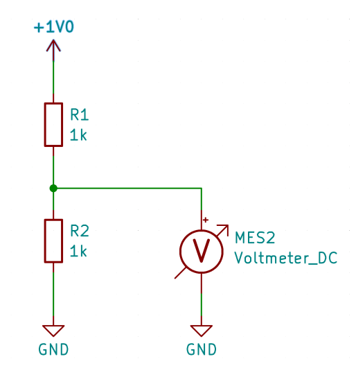
That's straightforward; we measure 0.5V. Now, let's consider a scenario where both resistors have a tolerance of 5%. In this case, R1 could have a resistance of 1050 ohms and R2 950 ohms, resulting in a voltage of 0.475V. Conversely, if the tolerance positions were reversed, with R1 at 950 ohms and R2 at 1050 ohms, the voltage would be 0.525V.
What's interesting here is that the average of these two voltage values, 0.475V and 0.525V, is exactly 0.500V - the nominal value. Armed with this knowledge, you can take two 1 kOhm resistors, conduct two measurements by swapping the resistors between the first and second measurements, and the average value will precisely correspond to half the voltage.
Now, let's address the issue of the measuring device. If, as mentioned earlier, a voltage divider with 0.1% tolerance measuring resistors is set up, the voltage variation in the worst-case scenario would be from 499.5mV to 500.5mV. If we aim to significantly improve this through calibration, say, by a factor of 10, we would require a resolution of 0.05mV in the 2,000V measuring range.
However, such precision is often beyond what's achievable in hobbyist laboratories. This is where the Wheatstone bridge comes into play to offer a solution.
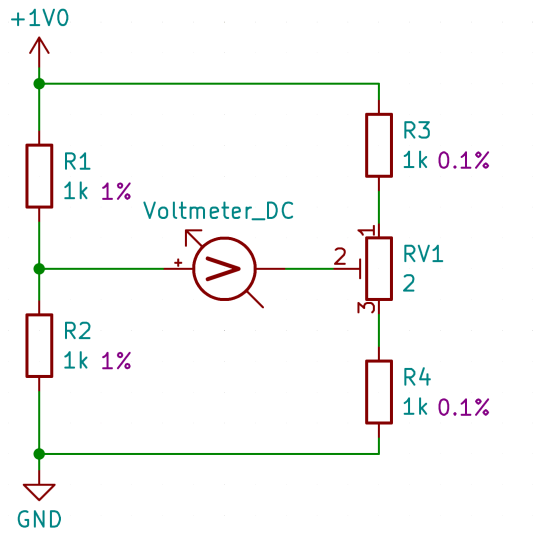
The voltage divider on the right, equipped with 0.1% measuring resistors, is to be calibrated using a reference setup on the left consisting of 1% resistors, aiming for a calibration accuracy surpassing 1%. At first glance, this might seem contradictory, but it's a method that indeed yields results.
Let's consider a scenario where the 'reference' resistors on the left, with a tolerance of 1%, have values of R1 = 990 Ohms and R2 = 1010 Ohms. On the right side, we have the measuring resistors with a tolerance of 0.1%, with values of R3 = 1001 Ohms and R4 = 999 Ohms. Additionally, there's a trimmer RV1 positioned in the middle, which represents a nearly worst-case scenario.
In this setup, we encounter the following situation:
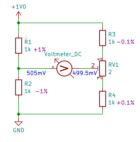
When we measure a voltage of 5.5mV using our measuring device with a resolution of 0.1mV in the 200mV measuring range, we gain insights into our calibration process. By swapping the two resistors, R1 and R2, and measuring again, we observe a voltage value of 495mV on the left, resulting in a difference of -4.5mV. The average of these measurements, 0.5mV, indicates that the voltage on the left at our 'reference' is 0.5mV higher, or conversely, our voltage at the measuring resistors is 0.5mV too low.
Adjusting the trimmer accordingly allows us to achieve the desired 0.5mV increase on the right, effectively modifying the voltmeter's display to reflect this adjustment. This means we read 5.5mV after 5mV or -4.5mV after -5mV.
In this example, the tolerances are symmetrical, at +1% and -1%, chosen to demonstrate the measuring range of the multimeter. However, this method works equally well with asymmetrical tolerances.
By calibrating with a resolution of 0.1mV, we've reached the upper limit of our resolution. Nevertheless, we still have room within our measuring range, with a maximum measurement of 5.5mV within a 200mV range. This allows us to scale up our voltage from 1V to 10V. Consequently, a resolution of 0.1mV proves sufficient to significantly enhance the accuracy of the 0.1% voltage divider, as the worst-case voltage range of ±5mV can be reduced to approximately ±0.1mV, using resistors with a 1% tolerance as our reference.
This demonstrates that through mathematical methods and procedures, we can establish references without relying on expensive measurement technology. Moreover, this calibration technique is not limited to achieving a factor of ½; any rational divisor ratio is attainable.
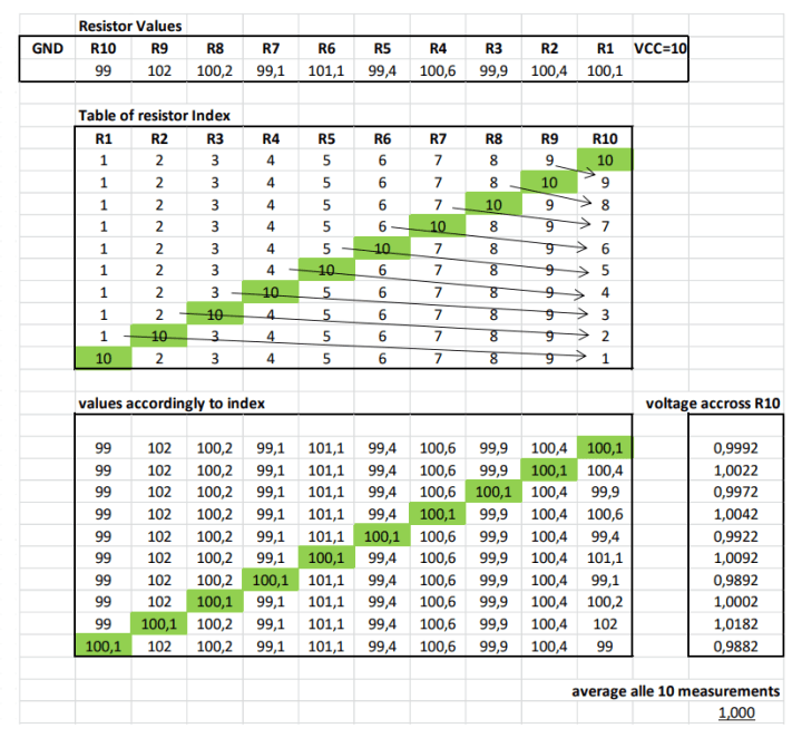
In the next example, we'll explore how to proceed if we aim for a ratio of 1/10. By permuting all resistors from the voltage divider for R10, we can confirm through calculations in an Excel table that the mean value indeed corresponds to 1/10, irrespective of the tolerance positions of the resistors.
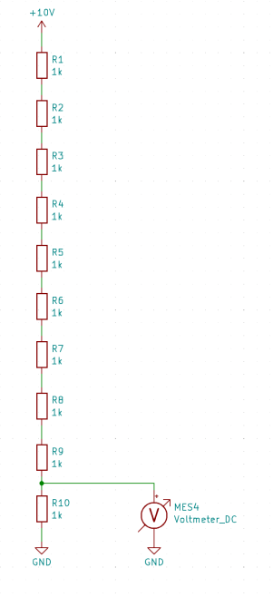
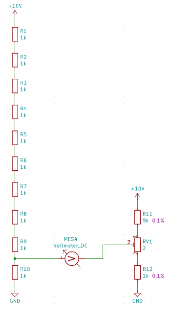
Here too, the voltage measurement is carried out in a Wheatstone bridge to increase the resolution when setting the measuring resistors.
Ultimately, this method provides a solution for setting any rational divisor ratio. However, it's worth noting that the complexity of the measuring process escalates notably when dealing with denominators and numerators greater than 1
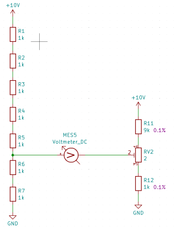
In this case, it's necessary to utilize all possible combinations for R6 and R7. However, considering the series connection of R6 and R7, it's evident that half of these combinations don't require measurement as their values are simply interchanged. In the table, references are made to positions higher up in the table, which represent equivalent series connections.
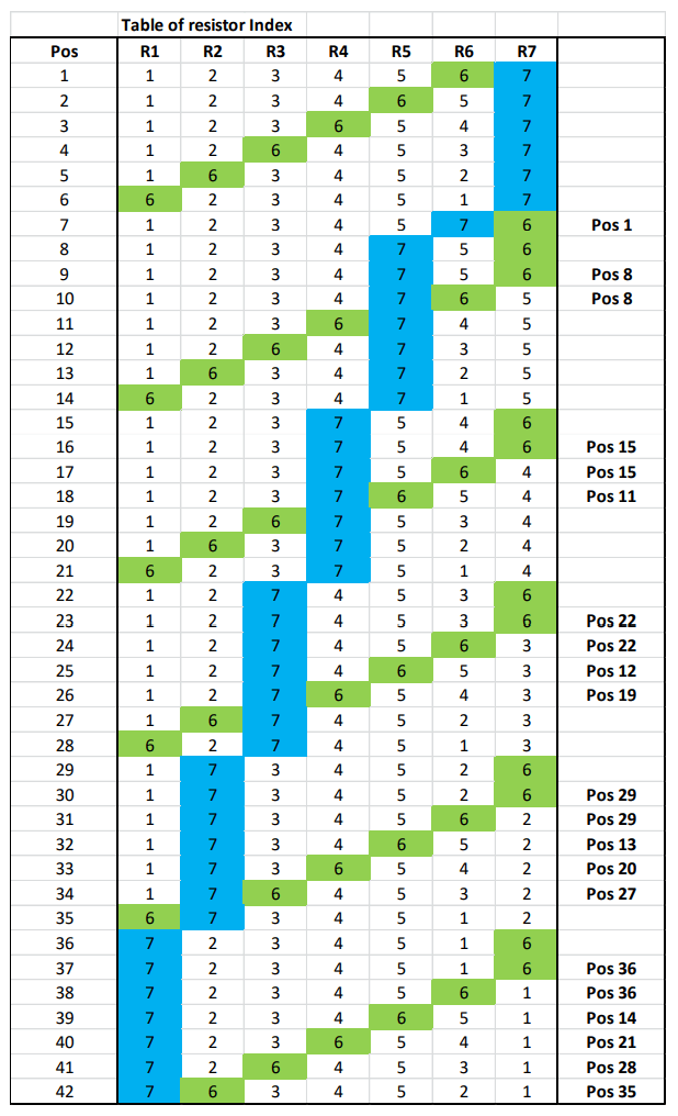
According to this sequence pattern, the average voltage across the series connection R6 + R7 will be exactly 2/7 of the input voltage. This requires 21 measurements in this case. The number of measurements results from m total number of resistors and n number of resistors across which the voltage is tapped.
number = m! / (m-n)! / n!
Application Examples:
Precision Voltage Divider: The described method can be applied to create precision voltage dividers, ensuring accurate voltage division for various applications.
Resistance Ratio for Gain Adjustment with Operational Amplifiers (OP): This technique can be used to set precise resistance ratios for gain adjustment in operational amplifier circuits, contributing to accurate signal processing.
ADC Linearity Test: The method can also be utilized for testing the linearity of Analog-to- Digital Converters (ADCs), ensuring accurate conversion of analog signals to digital data.
Conclusion:
This discussion highlights the availability of procedures that enable the attainment of precision through innovative methods. It emphasizes that possessing a measuring device of superior quality isn't always a strict requirement. This insight sheds light on the development process of devices, underscoring that these precision references weren't simply bestowed upon us but were likely achieved through similar procedural approaches. Even hypothetical scenarios involving extraterrestrial assistance would likely involve the use of such systematic methods.
Appendix:
Circuit Design:
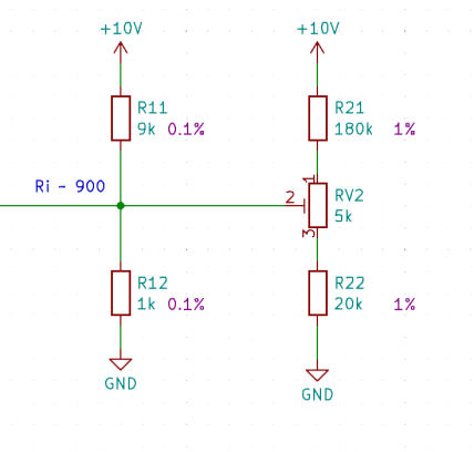
To create an adjustable voltage divider for measuring resistors with a tolerance of 0.1%, it's recommended to use corresponding resistors approximately 20 times larger in value. Additionally, the trimmer resistor should have a value approximately equal to 2 times the tolerance multiplied by the sum of R21 and R22, rounded up to the next available value.
This configuration allows for setting the trimmer within the tolerance range, providing a good resolution for adjustment. When the sliding contact is removed, the voltage drops to the value defined by the measuring resistors, ensuring the circuit remains closed and functional.
Calibration of precise voltage dividers without precise measuring equipment
When conducting calibration, it's common practice to utilize a measuring instrument that surpasses the accuracy of the object being calibrated by one classification. Typically, this involves using a measuring device with an error margin 5 to 10 times lower than that of the object.
For instance, if you're setting up a voltage divider with measuring resistors specified at 0.1% accuracy, the measuring instrument used for verification should ideally have a maximum error of 0.02% to 0.04%, depending on the set division factor.
However, it's often the case that hobbyist electronics engineers don't have access to such high- precision measuring equipment. In such scenarios, it's important to remember that innovative solutions can still be developed without relying on advanced measurement technologies. After all, many breakthroughs in calibration techniques were achieved without extraterrestrial intervention or access to ultimate references.
In this context, we present a procedure for calibrating a voltage divider without the need for precision measurement technology. How does it work? The key lies in mathematics. Let's begin by considering a simple voltage divider with equal resistors, R1=R2=1k Ohm
That's straightforward; we measure 0.5V. Now, let's consider a scenario where both resistors have a tolerance of 5%. In this case, R1 could have a resistance of 1050 ohms and R2 950 ohms, resulting in a voltage of 0.475V. Conversely, if the tolerance positions were reversed, with R1 at 950 ohms and R2 at 1050 ohms, the voltage would be 0.525V.
What's interesting here is that the average of these two voltage values, 0.475V and 0.525V, is exactly 0.500V - the nominal value. Armed with this knowledge, you can take two 1 kOhm resistors, conduct two measurements by swapping the resistors between the first and second measurements, and the average value will precisely correspond to half the voltage.
Now, let's address the issue of the measuring device. If, as mentioned earlier, a voltage divider with 0.1% tolerance measuring resistors is set up, the voltage variation in the worst-case scenario would be from 499.5mV to 500.5mV. If we aim to significantly improve this through calibration, say, by a factor of 10, we would require a resolution of 0.05mV in the 2,000V measuring range.
However, such precision is often beyond what's achievable in hobbyist laboratories. This is where the Wheatstone bridge comes into play to offer a solution.
The voltage divider on the right, equipped with 0.1% measuring resistors, is to be calibrated using a reference setup on the left consisting of 1% resistors, aiming for a calibration accuracy surpassing 1%. At first glance, this might seem contradictory, but it's a method that indeed yields results.
Let's consider a scenario where the 'reference' resistors on the left, with a tolerance of 1%, have values of R1 = 990 Ohms and R2 = 1010 Ohms. On the right side, we have the measuring resistors with a tolerance of 0.1%, with values of R3 = 1001 Ohms and R4 = 999 Ohms. Additionally, there's a trimmer RV1 positioned in the middle, which represents a nearly worst-case scenario.
In this setup, we encounter the following situation:
When we measure a voltage of 5.5mV using our measuring device with a resolution of 0.1mV in the 200mV measuring range, we gain insights into our calibration process. By swapping the two resistors, R1 and R2, and measuring again, we observe a voltage value of 495mV on the left, resulting in a difference of -4.5mV. The average of these measurements, 0.5mV, indicates that the voltage on the left at our 'reference' is 0.5mV higher, or conversely, our voltage at the measuring resistors is 0.5mV too low.
Adjusting the trimmer accordingly allows us to achieve the desired 0.5mV increase on the right, effectively modifying the voltmeter's display to reflect this adjustment. This means we read 5.5mV after 5mV or -4.5mV after -5mV.
In this example, the tolerances are symmetrical, at +1% and -1%, chosen to demonstrate the measuring range of the multimeter. However, this method works equally well with asymmetrical tolerances.
By calibrating with a resolution of 0.1mV, we've reached the upper limit of our resolution. Nevertheless, we still have room within our measuring range, with a maximum measurement of 5.5mV within a 200mV range. This allows us to scale up our voltage from 1V to 10V. Consequently, a resolution of 0.1mV proves sufficient to significantly enhance the accuracy of the 0.1% voltage divider, as the worst-case voltage range of ±5mV can be reduced to approximately ±0.1mV, using resistors with a 1% tolerance as our reference.
This demonstrates that through mathematical methods and procedures, we can establish references without relying on expensive measurement technology. Moreover, this calibration technique is not limited to achieving a factor of ½; any rational divisor ratio is attainable.
In the next example, we'll explore how to proceed if we aim for a ratio of 1/10. By permuting all resistors from the voltage divider for R10, we can confirm through calculations in an Excel table that the mean value indeed corresponds to 1/10, irrespective of the tolerance positions of the resistors.
Here too, the voltage measurement is carried out in a Wheatstone bridge to increase the resolution when setting the measuring resistors.
Ultimately, this method provides a solution for setting any rational divisor ratio. However, it's worth noting that the complexity of the measuring process escalates notably when dealing with denominators and numerators greater than 1
In this case, it's necessary to utilize all possible combinations for R6 and R7. However, considering the series connection of R6 and R7, it's evident that half of these combinations don't require measurement as their values are simply interchanged. In the table, references are made to positions higher up in the table, which represent equivalent series connections.
According to this sequence pattern, the average voltage across the series connection R6 + R7 will be exactly 2/7 of the input voltage. This requires 21 measurements in this case. The number of measurements results from m total number of resistors and n number of resistors across which the voltage is tapped.
number = m! / (m-n)! / n!
Application Examples:
Precision Voltage Divider: The described method can be applied to create precision voltage dividers, ensuring accurate voltage division for various applications.
Resistance Ratio for Gain Adjustment with Operational Amplifiers (OP): This technique can be used to set precise resistance ratios for gain adjustment in operational amplifier circuits, contributing to accurate signal processing.
ADC Linearity Test: The method can also be utilized for testing the linearity of Analog-to- Digital Converters (ADCs), ensuring accurate conversion of analog signals to digital data.
Conclusion:
This discussion highlights the availability of procedures that enable the attainment of precision through innovative methods. It emphasizes that possessing a measuring device of superior quality isn't always a strict requirement. This insight sheds light on the development process of devices, underscoring that these precision references weren't simply bestowed upon us but were likely achieved through similar procedural approaches. Even hypothetical scenarios involving extraterrestrial assistance would likely involve the use of such systematic methods.
Appendix:
Circuit Design:
To create an adjustable voltage divider for measuring resistors with a tolerance of 0.1%, it's recommended to use corresponding resistors approximately 20 times larger in value. Additionally, the trimmer resistor should have a value approximately equal to 2 times the tolerance multiplied by the sum of R21 and R22, rounded up to the next available value.
This configuration allows for setting the trimmer within the tolerance range, providing a good resolution for adjustment. When the sliding contact is removed, the voltage drops to the value defined by the measuring resistors, ensuring the circuit remains closed and functional.
Discussion (3 commentaire(s))