
Versatile Audio Amplifier with the Current Output Signal
A special sound of the transistor amplifier without the negative feedback loop
A negative feedback loop ensures linear characteristics of the audio amplifier. That's why the modern amps sound almost the same. The individuality is determined by the characteristic curves of the transistors and tubes. If you want a special sound, you should do without the negative feedback loop. B, AB and D amps have lot distortions. Therefore, only a class A amplifier can be used without the negative feedback loop. As headphone amplifier or preamp its energy consumption, however, will not be greater than 1W for two channels (stereo).
The proposed circuit is something special. The output signal is not voltage but current. The frequency dependence of load impedance is therefore irrelevant. This makes the sound more precise. It doesn't take much time to solder this amplifier circuit on a breadboard.
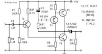
The input cascade is actually a voltage to current converter. The collector current of T1 is also the base current for driving T4. T2, T3 and C2 form a self-regulating current source and work as an internal load for T4.
There are two resistors R4* and R5* to be matched. To do this, T3 must first be removed. An auxiliary resistor 33Ω (corresponds to the headphone impedance) must be connected between the collector of T4 and +5V. By adjusting R4* the collector voltage of T4 is set to +2.5V. Then remove the auxiliary resistor and solder T3. After switching on it takes a few seconds for C2 to charge and T3 to start conducting. The collector voltage of T3 and T4 is set to +2.5V with R5*. The adjustment is complete.
The clipping takes place at 1.2V RMS and is very soft. The 2nd harmonic accounts for most of the distortion. It increases with the amplitude of the signal and reached 5% at the output voltage of 1V RMS.
Should this amp be used as a preamp, its output must be loaded with resistor >33Ω. The greater the resistance, the greater the voltage gain. In fact, in this case you can save power consumption by using the auxiliary resistor for the adjustment
with the larger resistance, e.g. instead of 33Ω you take 1k. Then the voltage gain is approximately calculated as the load resistance divided by 1k.
The amplifier can also be used to drive a loudspeaker. For this the auxiliary resistor for the adjustment must have approximately the same resistance as the loudspeaker, e.g. 8.2Ω. Aside from that the more powerful transistors should be used, e.g. TIP32 for T3 and TIP31 for T4, and C3 can be increased to 2200µF.
Because the output signal is current and it is limited, the amplifier is short-circuit proof and the load is also protected.
The proposed circuit is something special. The output signal is not voltage but current. The frequency dependence of load impedance is therefore irrelevant. This makes the sound more precise. It doesn't take much time to solder this amplifier circuit on a breadboard.
The input cascade is actually a voltage to current converter. The collector current of T1 is also the base current for driving T4. T2, T3 and C2 form a self-regulating current source and work as an internal load for T4.
There are two resistors R4* and R5* to be matched. To do this, T3 must first be removed. An auxiliary resistor 33Ω (corresponds to the headphone impedance) must be connected between the collector of T4 and +5V. By adjusting R4* the collector voltage of T4 is set to +2.5V. Then remove the auxiliary resistor and solder T3. After switching on it takes a few seconds for C2 to charge and T3 to start conducting. The collector voltage of T3 and T4 is set to +2.5V with R5*. The adjustment is complete.
The clipping takes place at 1.2V RMS and is very soft. The 2nd harmonic accounts for most of the distortion. It increases with the amplitude of the signal and reached 5% at the output voltage of 1V RMS.
Should this amp be used as a preamp, its output must be loaded with resistor >33Ω. The greater the resistance, the greater the voltage gain. In fact, in this case you can save power consumption by using the auxiliary resistor for the adjustment
with the larger resistance, e.g. instead of 33Ω you take 1k. Then the voltage gain is approximately calculated as the load resistance divided by 1k.
The amplifier can also be used to drive a loudspeaker. For this the auxiliary resistor for the adjustment must have approximately the same resistance as the loudspeaker, e.g. 8.2Ω. Aside from that the more powerful transistors should be used, e.g. TIP32 for T3 and TIP31 for T4, and C3 can be increased to 2200µF.
Because the output signal is current and it is limited, the amplifier is short-circuit proof and the load is also protected.
Mises à jour de l'auteur