
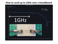
How to send up to 1 GHz over a breadboard
Transmission up to 1 GHz over a breadboard allows testing without soldering. An example measuring selfresonance of capacitors is shown. This project also introduces the use of a very lowcost RF-networkanalyzer.
Flat transmission within 1dB up to 1 GHz over a breadboard including the use of wire bridges is demonstrated here. In the uploaded document several applications and detailed measurements are shown. A movie shows the basics in short:
https://www.youtube.com/watch?v=lZFKHF7NOs0
Using a breadboard for high frequency applications
is commonly seen as not possible. There are indeed quite some limitations, like: no groundplane, crosstalk to adjacent contact strips, wires that form inductors. Here it is shown that with simple homemade adapters you can transmit signals up to 1GHz over a few cm of breadboard traces and wire bridges. Transmission, reflection and crosstalk (signal wire bridge removed) are measured, giving quite acceptable results. An application for measuring selfresonance of capacitors is shown. I made up the concept to first evaluate the noise performance of a 400MHz optical detector before deciding to design a PCB for it (the breadboard was placed in a shielded box for this).
The concept of getting a proper RF transmission
over the breadboard is based on creating a so-called coplanar transmission line, this does not need a groundplane underneath. Basically you run the centre conductor with an adjacent ground line on each side of it. A look at a breadboard layout reveals that this is possible using in total 3 neighbouring contact strips. A test showed that you can even "jump over" with 3 wire bridges to strips at the other side of the board while maintaining a transmission that is flat without 1dB up to 1GHz.
Some measured values using the adapters and wire bridges:
(measured traces can be found in the uploaded document)
Transmisson (named S21) is worst case only down with -0.9dB at 1GHz.
Reflection (named S11) is highest -12dB at 1GHz and below -16dB at other frequencies. This means the reflected power because of mismatches in the transmission is less than 6%.
Crosstalk with central wire bridge removed (S21 again) is worst case -21dB when approaching 1GHz and -40dB at 500MHz
This means that even at 1GHz, less than 1% of the power leaks from one side to the other side.
Basics of the equipment used here:
This unit is called a VNA, a Vector Network Analyzer, capable of measuring RF transmission and reflection. This one has two signal connectors , these are called "ports" in VNA language. Port 1 can both send and receive a signal, Port 2 can only receive a signal.The unit measures magnitude and phase (that is what the "Vector" stands for) of the signals on these ports. It's measurement range spans from 50kHz up to maximum 6.3GHz.
With a VNA you can measure RF-transmission, named S21, meaning: what is port 2 receiving from port 1, and also RF-reflection, named S11, meaning: what is port 1 getting back from it's own send signal. Much more is possible, in the uploaded document several applications are shown.
Some info on the specific VNA used here:
Up to some years ago you could only buy professional VNA's at prices above 10k Euro. Some clever HAM radio amateurs developed a small unit with a bit restricted specs but enough for most applications. These models are called NANO-VNA and Lite-VNA (used here) and start at prices around 100 Euro. The tiny units can work stand-alone but also come with free software to operate and read them from a PC.
Want to build a project?
Bring your design to life with the Elektor PCB Service, powered by Eurocircuits. Upload the project files and order professionally manufactured PCBs or assembled boards through a proven European production platform.
Supporting KiCad, Eagle, Gerber, and ODB++ formats, the service is suitable for everything from prototypes and validation builds to series production and volume manufacturing.
Made in Europe. Fast. Reliable. Professional.
Discussion (0 commentaire(s))