Illuminated Cubes that randomly fade-in and fade-out.
Introduction
At home we have two illuminated presents, that look like cubes, which are used during the Christmas period. These are simple illuminated presents using a 2 color red-green LED that randomly change color which fade in and fade out. The device is powered by a 3 Volt button cell. The latter was the reason for this project since the battery is depleted very quickly when the presents are powered on for a longer time.
As to prevent the usage of a huge amount of button cell batteries I designed my own version using three rechargeable AAA batteries. I also created two cubes with different sizes. It uses an RGB LED so blue is also possible but that was not part of the original design. My version has the following functions:
Control 2 Cubes at the same time using one PIC12F617 microcontroller. The microcontroller software was written in the JAL programming language
Switch the Cubes on and off using a push button
Randomly change the color of the Cubes independently by fade-in and fade-out of the colors red and green and sometimes both Cubes are blue.
Switch off the Cubes when the battery voltage drops below 3.0 Volt. This will prevent the rechargeable batteries from being discharged too much
After fading-in one color, the LED stays on for a time somewhere between 15 seconds and 30 seconds. Since I still had the unused blue LED I added the feature that both Cubes will turn blue when the on-time is exactly 20 seconds. This does not happen very often since the random time is generated in timer ticks of 40 milliseconds as described later.
The fading-in and fading-out uses Pulse Width Modulation (PWM). Since the Cubes are of different sizes, I used 3 LEDs for the big Cube and 1 LED for the smaller Cube. In order to make both Cubes shine with the same brightness, I limited the maximum on-time of the PWM of both Cubes. Since the Cubes where a bit brighter than required, this brightness limitation also extends the operation of the – rechargeable – batteries.
The mechanical work
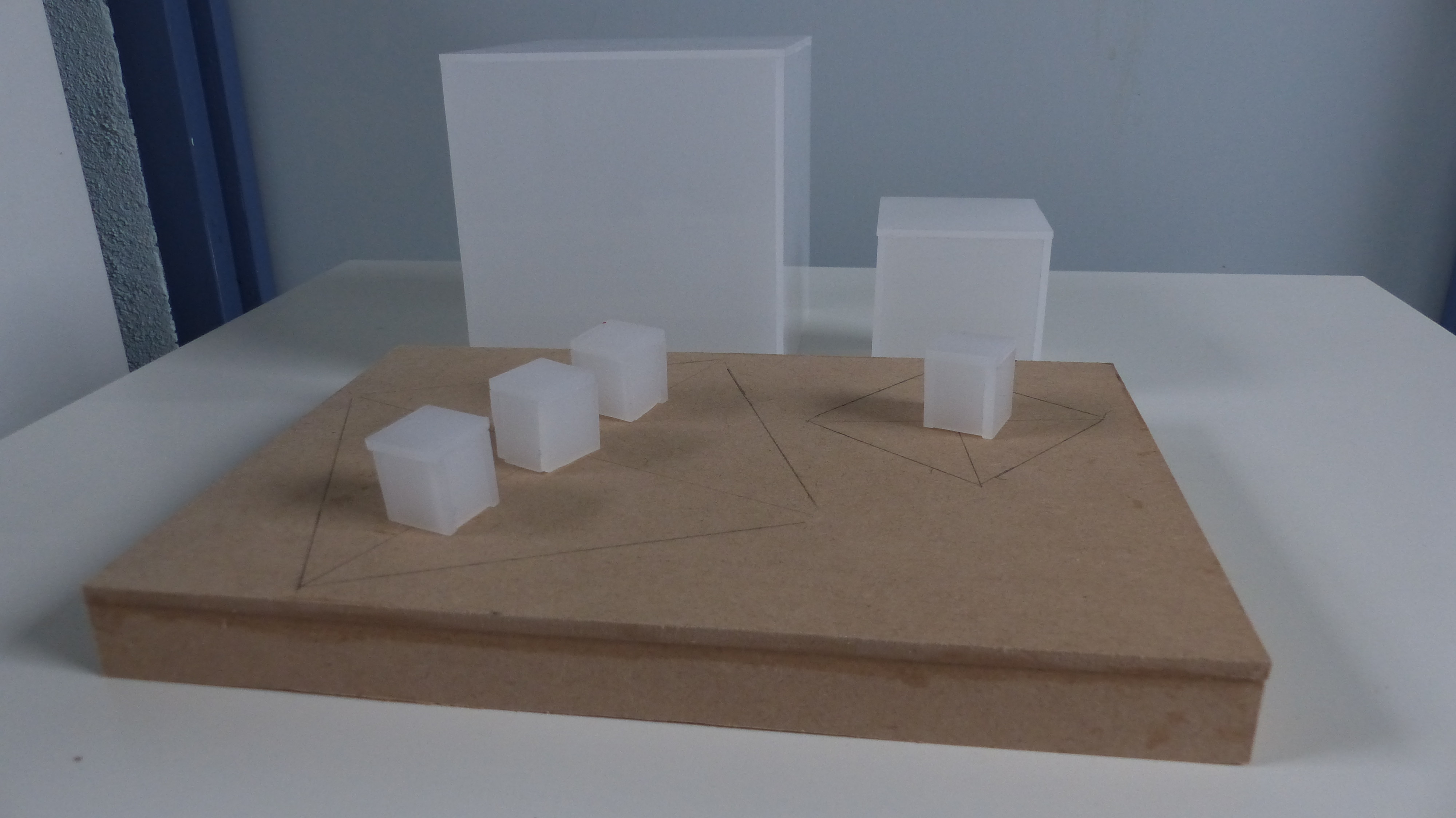
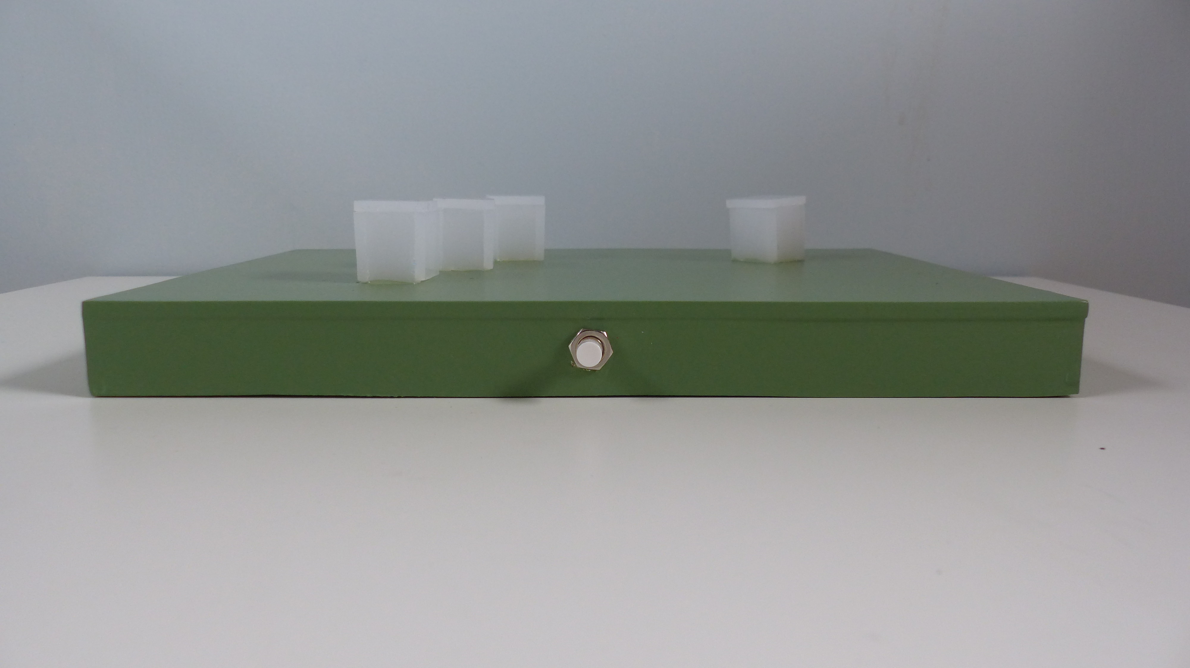
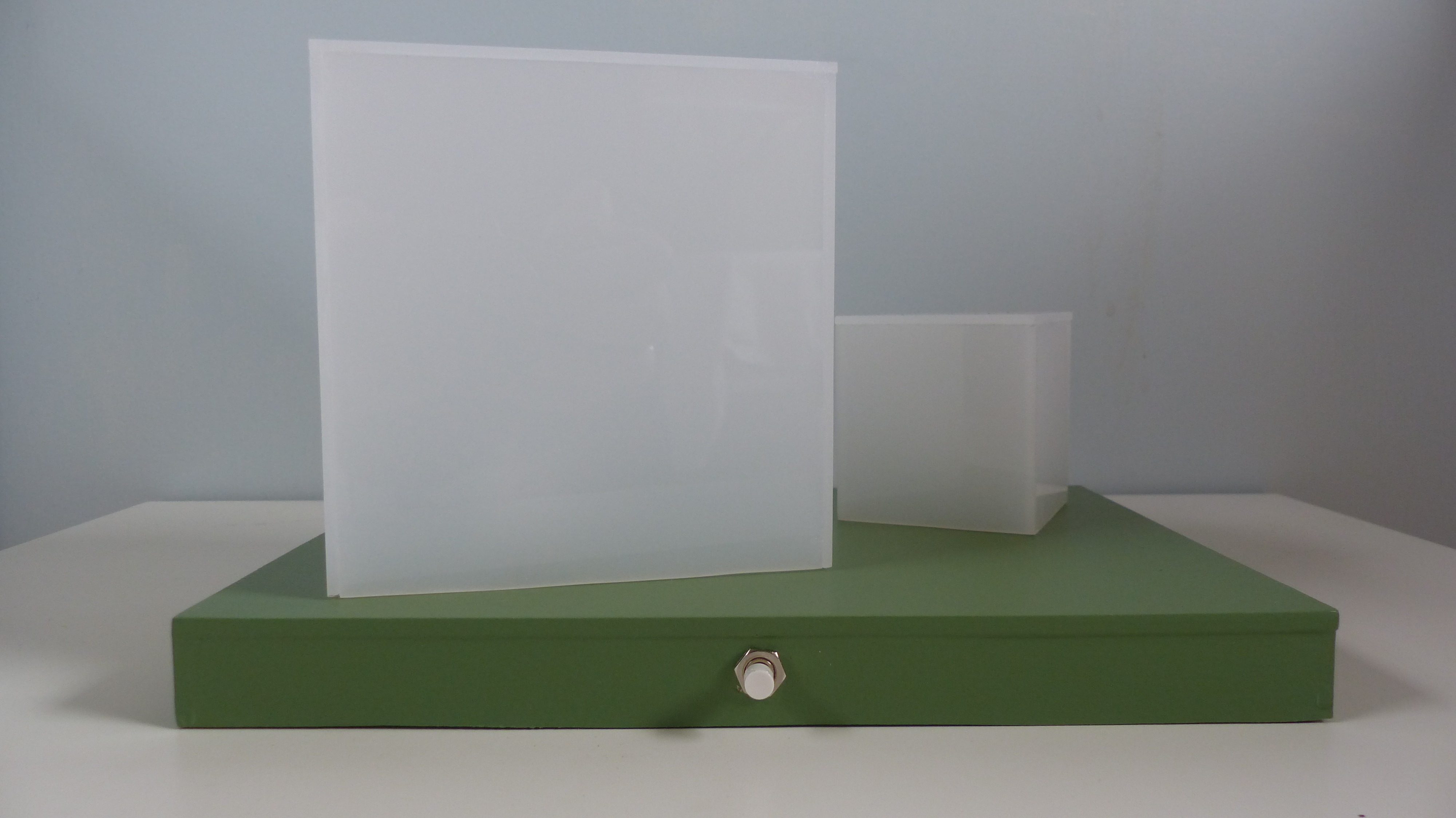
For making the Cubes I used milk white acrylic plastic and for the rest of the set-up I used MDF. As to prevent that you see the shape of the LED in the Cubes when the LED is on, I put a cover on top of the LEDs that diffuses the light from the LED. This time I made the cover by creating small Cubes using the same acrylic plastic. In the pictures you see the results.
The electronics
The schematic diagram shows the electronic components you need. Since I am using more LEDs for the bigger Cube I needed some transistors to drive them since the PIC cannot drive three LEDs on one port. The electronics is powered by a 3 AA(A) rechargeable batteries and can be powered on or off by pressing the reset switch.
You need the following electronic components for this project:
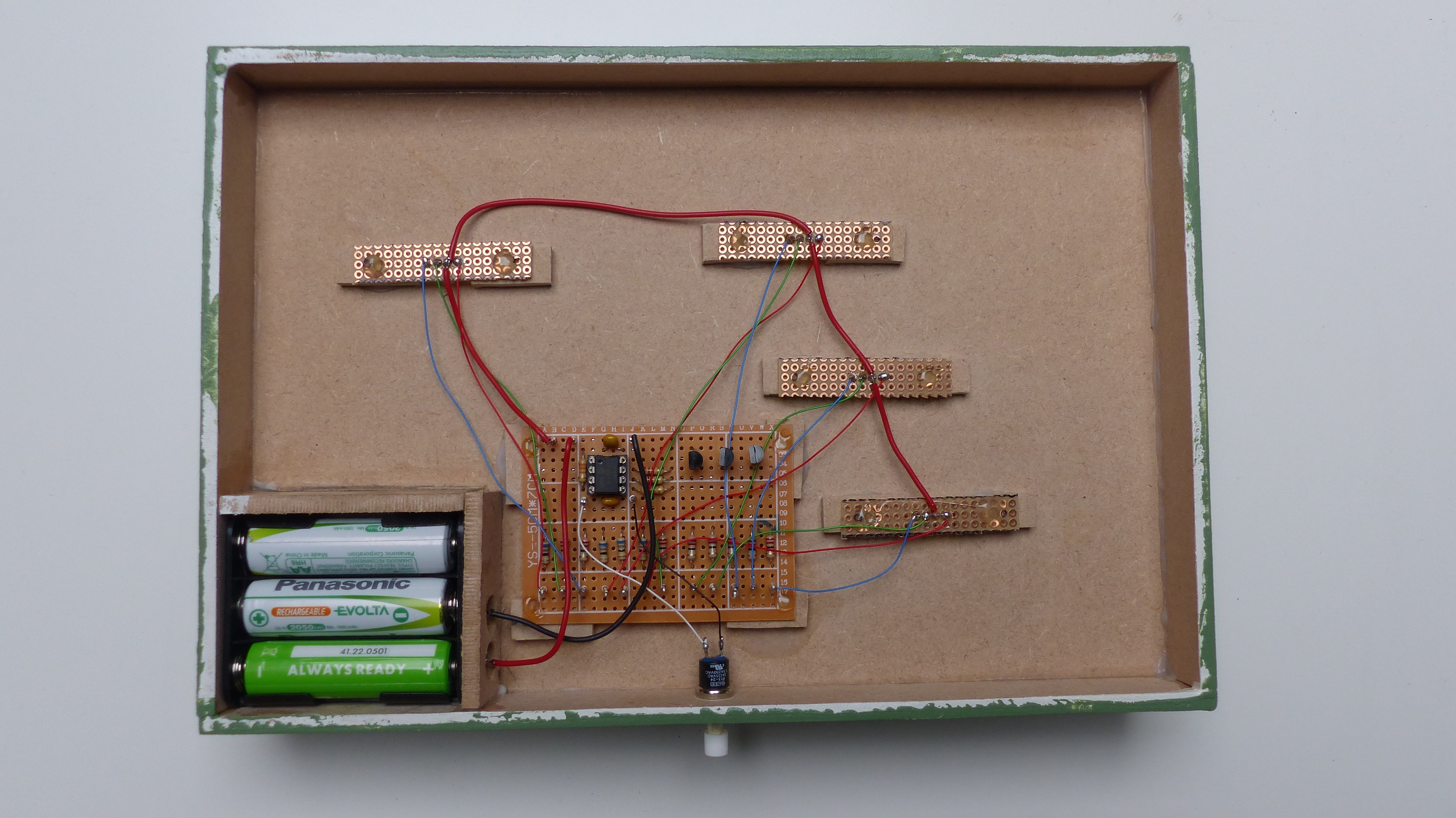
You can build the circuit on a breadboard and does not require much space, as can be seen in the picture. You may wonder why the resistor values for controlling the maximum current through the LEDs are so low. This is because of the low supply voltage of 3.6 Volt in combination with the voltage drop that each LED has, which depends on the color per LED, also see: https://en.wikipedia.org/wiki/LED_circuit. With these resistor values and when the brightness it at its maximum the maximum current of the whole system is around 40 mA. I limited the maximum on-time as mentioned earlier so for this version the maximum current is less than 20 mA.
The software
The software performs the following tasks:
When the device is reset by the push button it will turn the device on if it was off or it turns the device off if it was on. Off means putting the PIC12F617 into sleep mode in which it hardly consumes any power.
Generate the PWM signal to control the brightness of the LEDs. This is done using a timer and an interrupt service routine that controls the pins of the PIC12F617 who on their turn the LEDs on and off.
Fade-in and fade-out the LEDs and keep them on for a random time between 15 and 30 seconds. If the random time equals 20 seconds, both LEDs will turn blue for 20 seconds after which the normal red-green fade-in and fade-out pattern is used.
During operation the PIC will measure the supply voltage using its on-board Analog to Digital Converter (ADC). When this voltage drops below 3.0 V, it will switch the LEDs off and will put the PIC into sleep mode again. The PIC could still operate well at 3.0 V but it is not good for the rechargeable batteries to be completely drained.
As mentioned earlier the PWM signal is created using a timer that uses an interrupt service routine as to keep a stable PWM signal. The fading-in and fading-out of the LEDs including the time the LEDs are on, is controlled by the main program. This main program uses a timer tick of 40 milliseconds, derived from the same timer that creates the PWM signal.
Since I did not use any specific JAL libraries for this project this time I had to make a random generator using a linear feedback shift register for generating the random on time and random off time of the LEDs.
The JAL source file and the Intel Hex file for programming the PIC are attached.
The final result
The final result can be seen in this video. Note that green looks more like light blue but you get the picture. Also the strange pattern seen on the video is caused buy the camera and is not visible
If you are interested in using the PIC microcontroller with JAL – a Pascal like programming language – visit the JAL website.
Have fun making this project and looking forward to you reactions and results.
Want to build a project?
Bring your design to life with the Elektor PCB Service, powered by Eurocircuits. Upload the project files and order professionally manufactured PCBs or assembled boards through a proven European production platform.
Supporting KiCad, Eagle, Gerber, and ODB++ formats, the service is suitable for everything from prototypes and validation builds to series production and volume manufacturing.
Veuillez saisir votre adresse électronique. Les instructions de réinitialisation de votre mot de passe vous seront immédiatement envoyées par courriel.




Discussion (0 commentaire(s))