
Making a Party Soundbox
Now let's make our parties(birthday or new year parties) more enjoying and luxurious with a soundbox.
Introduction
Here I am going to show you how you can build a DIY sound box for using in your birthday or new year parties. This 10W soundbox(Party box) is enough to make your parties more enjoying and marvelous. The size and weight of the party box is not much so you can easily take it anywhere along with you. The cost of this party box is also not very high in comparison to readymade party boxes. I have also used bass and treble control here so you can adjust the bass & treble according to your desire. This party box requires 220V/50Hz AC mains supply for working. I have not used a battery here so you can't use it without electricity. In my future improvements, I will also use a battery inside the box so that it can be used without mains 220V supply.
Components List
Transistors
Resistors
18-0-18/3amp(with center tap)
12V/1amp(without center tap)
Loudspeaker
4 ohm/25W
Tools
Tone Control Circuit
I am using an active baxandall tone control circuit as pre amplifier and tone control. Tone control circuit consists of three transistors(BC548B). First two transistors are used as emitter follower(or buffer amplifier) and the third transistor is used as common emitter amplifier. The output of the third transistor of tone control circuit drives the power amplifier circuit. In this circuit there are three 100K potentiometers for treble, bass and volume control.
Power Amplifier Circuit
To make the power amplifier circuit, I am using only bipolar junction transistors. There are total eight transistors in power amplifier circuit. Q1 and Q2 are attached on heatsink because they are power transistors and gets hot during use. Q1 and Q2 both are npn transistors. Transistors Q3 and Q4 is used to the Q1 and Q2 transistors respectively. Transistor Q6 is used as Vbe multiplier to bias the base of transistors Q3 and Q4. It is necessary to properly bias the base of Q3 and Q4 otherwise amplified signal will be distorted(crossover distortion will occur). Transistors Q3 and Q4 are operated in class AB mode. Q5 is a class driver transistor to drive the output stage or push-pull stage of the power amplifier. The base of Q5 is connected to the output of differential amplifier. Transistors Q7 and Q8 forms a differential amplifier stage. Q8 and Q7 are pnp transistors. Input signal is applied to the base of transistor Q8 and feedback signal is applied to the base of transistor Q7. The voltage gain of the power amplifier can be calculated by the following expression:
Voltage gain = {1+(R11/R12)}
R11 = 15K ohm, R12 = 150 ohm
hence,
Voltage gain = {1+(15000/150)}
= 1+100
= 101
The power amplifier circuit requires floating ground dc power supply of 18V. Maximum output power of the power amplifier is 34.4 Watts
Pout(Max.) = 34.4 Watts.
Power Supply
For supplying the DC power to the power amplifier, I am using a 18-0-18V/3A type transformer. The tone control circuit and vu meter circuit require 12V DC supply so I decided to use a LM7812 Voltage regulator to convert +18V to +12V but recently I do not have LM7812 IC so I am using a separate power supply for tone control & vu meter circuits.
I take a second 12-0-12 transformer to power the tone control and vu meter circuit. Then I connected the primary windings of both transformer parallelly to a main lead.
VU Meter Circuit
I am using KA2284 IC to make the vu meter circuit. I can drive 5 LEDs and requires very less external components. This IC is available in single inline package(SIP). Input to the vu meter circuit is given from the output of the power amplifier.
10W Speaker
Although I am using a 25W power amplifier to drive the loudspeaker but I did not found any 25W or more powerful loudspeaker in my collection of loudspeakers so I am using a 10W loudspeaker here. The specifications of the loudspeaker are listed below:
To prepare the cabinet for loudspeaker, I am using a cardboard box. I got my cardboard box from amazon as online parcel. To fit the loudspeaker in cabinet put the loudspeaker on one of the faces of the box and then draw the outline with the help of pencil. Now also highlight the indentation area with the pencil and cut out all the area rounded by indentation. Again fit the loudspeaker in the hole of cabinet and this time mark the positions of screws. Drill the four marked holes for M4 bolts. Finally Fit the loudspeaker in the cabinet hole with the help of M4 nut and bolts for ever. During rotating the bolts with screwdriver please keep patience otherwise you will destroy the diaphragm of the loudspeaker.
Here I am going to show you how you can build a DIY sound box for using in your birthday or new year parties. This 10W soundbox(Party box) is enough to make your parties more enjoying and marvelous. The size and weight of the party box is not much so you can easily take it anywhere along with you. The cost of this party box is also not very high in comparison to readymade party boxes. I have also used bass and treble control here so you can adjust the bass & treble according to your desire. This party box requires 220V/50Hz AC mains supply for working. I have not used a battery here so you can't use it without electricity. In my future improvements, I will also use a battery inside the box so that it can be used without mains 220V supply.
Components List
Transistors
- 2N3055
- BD139
- BD140
- BC548B
- BC558B
- 1N5408
- 1N4007
- 9V Zener diode
- 2200UF/25V
- 47UF/63V
- 4.7UF/63V
- 1000UF/16V
- 2.2NF
- 220PF
- 0.047UF
- 0.1UF
- 100UF
- 10UF/63V
Resistors
- 0.1/5W
- 2.2/0.5W
- 10/1W
- 100
- 150
- 680
- 1k
- 1.5k
- 2.2k
- 2.7k
- 3.3k
- 4.7k
- 5.6k
- 6.8k
- 10k
- 15k
- 22k
- 47k
- 100k
- 270k
- Potentiometers
- 100k
- 470k
- Red(5mm)
- Yellow(5mm)
- Green(5mm)
18-0-18/3amp(with center tap)
12V/1amp(without center tap)
Loudspeaker
4 ohm/25W
Tools
- Soldering iron(60W)
- Soldering wire
- Soldering flux
- Scissors
- Wire cutter
- Tweezers
- Screw driver
- PCB terminals
- JST connectors
- Heat sink for 2N3055 power transistors.
- 3.5mm AUX cable
- Main Lead
- M3 nut-volts
- Cardboard box
- KA2284 IC
- PCB(printed circuit board)
Tone Control Circuit
I am using an active baxandall tone control circuit as pre amplifier and tone control. Tone control circuit consists of three transistors(BC548B). First two transistors are used as emitter follower(or buffer amplifier) and the third transistor is used as common emitter amplifier. The output of the third transistor of tone control circuit drives the power amplifier circuit. In this circuit there are three 100K potentiometers for treble, bass and volume control.
Power Amplifier Circuit
To make the power amplifier circuit, I am using only bipolar junction transistors. There are total eight transistors in power amplifier circuit. Q1 and Q2 are attached on heatsink because they are power transistors and gets hot during use. Q1 and Q2 both are npn transistors. Transistors Q3 and Q4 is used to the Q1 and Q2 transistors respectively. Transistor Q6 is used as Vbe multiplier to bias the base of transistors Q3 and Q4. It is necessary to properly bias the base of Q3 and Q4 otherwise amplified signal will be distorted(crossover distortion will occur). Transistors Q3 and Q4 are operated in class AB mode. Q5 is a class driver transistor to drive the output stage or push-pull stage of the power amplifier. The base of Q5 is connected to the output of differential amplifier. Transistors Q7 and Q8 forms a differential amplifier stage. Q8 and Q7 are pnp transistors. Input signal is applied to the base of transistor Q8 and feedback signal is applied to the base of transistor Q7. The voltage gain of the power amplifier can be calculated by the following expression:
Voltage gain = {1+(R11/R12)}
R11 = 15K ohm, R12 = 150 ohm
hence,
Voltage gain = {1+(15000/150)}
= 1+100
= 101
The power amplifier circuit requires floating ground dc power supply of 18V. Maximum output power of the power amplifier is 34.4 Watts
Pout(Max.) = 34.4 Watts.
Power Supply
For supplying the DC power to the power amplifier, I am using a 18-0-18V/3A type transformer. The tone control circuit and vu meter circuit require 12V DC supply so I decided to use a LM7812 Voltage regulator to convert +18V to +12V but recently I do not have LM7812 IC so I am using a separate power supply for tone control & vu meter circuits.
I take a second 12-0-12 transformer to power the tone control and vu meter circuit. Then I connected the primary windings of both transformer parallelly to a main lead.
VU Meter Circuit
I am using KA2284 IC to make the vu meter circuit. I can drive 5 LEDs and requires very less external components. This IC is available in single inline package(SIP). Input to the vu meter circuit is given from the output of the power amplifier.
10W Speaker
Although I am using a 25W power amplifier to drive the loudspeaker but I did not found any 25W or more powerful loudspeaker in my collection of loudspeakers so I am using a 10W loudspeaker here. The specifications of the loudspeaker are listed below:
- Power(R.M.S.)------------------>10W
- Power(Max.)-------------------->15W
- SPL 1W@1M------------------->95dB
- Nominal Diameter------------>156mm(6'')
- Frequency Response-------->65Hz - 15,000Hz
- Magnet---------------------------->72 x 32 x 15
- Weight----------------------------->0.525Kg
- Cone-------------------------------->Paper Edge
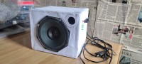
To prepare the cabinet for loudspeaker, I am using a cardboard box. I got my cardboard box from amazon as online parcel. To fit the loudspeaker in cabinet put the loudspeaker on one of the faces of the box and then draw the outline with the help of pencil. Now also highlight the indentation area with the pencil and cut out all the area rounded by indentation. Again fit the loudspeaker in the hole of cabinet and this time mark the positions of screws. Drill the four marked holes for M4 bolts. Finally Fit the loudspeaker in the cabinet hole with the help of M4 nut and bolts for ever. During rotating the bolts with screwdriver please keep patience otherwise you will destroy the diaphragm of the loudspeaker.
Discussion (2 commentaire(s))