
My Self-built Theremin
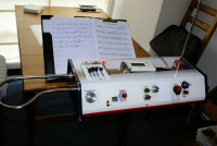
During the year 2008 I first met the Theremin. When I heard Lydia Kavina playing her theremin I was totally smitten. My desire was to have also such an instrument. Because the commercially available theremins (mostly by Moog Inc.) were too expensive for me, I decided to develop a theremin of my own. 2013 I had my own instrument in concert quality. Lydia, during a visit to Colmar (Alsace) played it and found its sound very beautiful. I have had some lessons from her and also from her master students Caro
My theremin has three oscillators: The pitch oscillators (one local and one variable oscillator) and an oscillator for the volume circuitry.
All my electronics I have developed myself from scratch following some basic principles which I learnt from the Internet.
Assisted by LTspice I built up my oscillator circuits and improved them step by step until I achieved not only a satisfying but a perfect function.
The LC oscillators of my prototype theremin work at 530 kHz. The antenna circuit is a serial circuit consisting of two coils with a tiny trimming capacitor between both coils. If you meet the proper resonance frequency, the spherical pitch field will get far more cylindrical and well linearized.
My theremin has a audio range from below 20 Hz to about 5 kHz.
I drew the circuit boards with Microsoft Paint. It's a simple program but its simplicity was helpful for getting straight lines and clear structures on the boards.
Of course, I printed and etched all my boards myself with a self-built etching system.
The volume oscillator works at 467 kHz and needed a very sharp filter circuitry around the LT1220 amplifier by Linear Technology.
Detuning by hand, the frequency drops quite deeper than in the pitch circuitry. The filter circuit (serial filter in the primary stage, parallel filter in the OP feedback loop) lowers the amplitude of the signal dramatically so that the sound is muted when the hand is in or tightly above the loop antenna.
By rising the left hand the volume increases by 100 dB due to the voltage controlled amplifier SSM2164.
The pitch signal is obtained by three demodulator circuits: ring modulator, diode demodulator, and a subminiature pentode 1T4 with 70 V anode voltage and 50 mA heating current.
The three signals are adjustable with a mixing desk to obtain a beautiful sound.
Contrary to the market leader Moog my theremin has a unique frequency stability and keeps its settings over years because I use high quality components, for instance glimmer capacitors and ferrite potcore inductances for the frequency determining circuits.
The Moog Etherwave detunes itself within some months or even weeks and needs to be readjusted by skilled people.
In my theremin I have installed a very fine and stable pitch correction, developed, of course, by myself.
Discussion (1 commentaire(s))