No microcontrollers, no chips, no transistors. Just a digital clock. The only silicon is in the glass of the tubes
No-Si digital clock with digital readout 0:00-11:59 TOTALLY WITHOUT SILICON. No microcontrollers, no chips, no transistors. The only silicon is in in the glass of the tubes! Figure 1. The nixie readout unit
Introduction
This project is about a digital clock with nixie tube readout in valve (tube) technology. I have used absolutely NO SILICON TRANSISTORS or chips, let alone a microcontroller. I have used 7 germanium diodes to keep the tube count acceptably low. The 1Hz frequency is derived from the mains frequency (50/60Hz). Frequency division and counting the minutes and hours is done with dekatrons.
I have done numerous clock projects in the past, some with nixie readout and some with other technology. I wanted to challenge myself and decided to go No-Si. This is now a finished, working project. The schematic diagram is available in the Files section (Kicad). Also the physical design of the aluminium base plate is available there (FreeCad). Check out the video below.
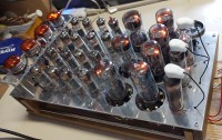
The objective of the No-Si-Clock is a digital clock with nixie tube readout in valve/tube technology, while using no other silicon than the silicon in the glass envelopes of the tubes. In total I have used 31 tubes in this project, some vacuum and some gas-filled. Figure 2. A forest of tubes. One can clearly see the neon discharge in the dekatrons (the larger tubes)
The block diagram (see the KiCad project in the files section) contains:
Power supply block
One BPM generator block
Unit minutes block
Tens minutes block
Hours block
The design encompasses seven dekatrons, which are the counting elements. A dekatron is a neon-filled tube, with one anode and a great number of cathodes (typically 30), arranged in a circle. At any moment in time, a discharge is present at one of the cathodes and as long as nothing happens, the discharge continues on that cathode. This makes the dekatron a memory element. Ten of the cathodes represent a stable state, while the other 20 are transient. These 20 are connected together in two groups of 10 and by applying negative impulses to these groups, the neon discharge can be transferred from one to the next stable cathode. This makes the dekatron a counting element. The dekatron also has one of more outputs, each of which generates an impulse once per revolution. Figure 3. The project in an intermediate state
· One dekatron is used to divide the mains frequency by 5 and then by 10. This results in 1Hz.
· There is another type of dekatron, that can count to 12 and can also be used to divide by 6.
· Starting with 50 Hz (or 60 Hz) mains frequency, the dekatrons will do the following.
· Dekatron type 6802 (or GS12C) divides by 5 (or 6) -> 10Hz
· Dekatron type 6802 divides by 10 -> 1Hz... Hurraah!
· Dekatron type 6802 divides by 10 -> one impulse per 10 seconds
· Dekatron type GS12C divides by 6 -> one impulse per minute
· Dekatron type GS10C divides by 10 -> drives the minute units and outputs an impulse per 10 minutes
· Dekatron type GS12C divides by 6 -> drives the 10 minutes and outputs an impulse per hour
· Dekatron type GS12C divides by 12 -> drives the hours
Figure 4 The "one beat per minute generator". Mains frequency 50Hz is divided by 5, 10, 10 and 6.
The first stage divides the mains frequency (50 or 60Hz) by 5 (or 6). In principle, this is just a 'dekatron spinner' circuit, like the ones that can be found on the internet. But the difference is that the output impulse from 2 of the dekatron's cathodes is taken, amplified and inverted by one of the triodes in a E90CC double triode. For each rotation of the spinner, two such impulses are generated (10Hz) and fed to the second stage, which divides the frequency by 10, which gives a one Hertz (1 Hz) impulse.
The stages that drive the nixies, pose an extra problem. The outputs of the dekatron are not suitable to drive the nixies just like that. The signals need to be amplified and inverted. This will be handled by the E90CC's. These double triodes were specifically designed back in the day for computer and other digital purposes. They are unsuitable for audio applications, among others because the suffer from microphony, and that's very nice because that keeps the price down. I was able to lay my hands on the required number of E90CC's for €2 each.
Figure 5 Driving a nixie tube from a dekatron requires 10 triodes.
If you study Figure 1and Figure 2 carefully, you will notice that the coupling between the stages is done using a 2.2nF capacitor. This is to decouple the high anode voltage from the rest of the circuit. This leads to short impulses. This is typical of digital tube technology and different from what we are used to in transistor and IC technology. Nowadays dc-coupling, without a capacitor is the norm. An added advantage of ac-coupling in this circuit is that the power consumption (in the triode and its anode resistor) is lower, because the triode only opens briefly.
However, the circuit that drives the nixie tubes in Figure 2 cannot rely on ac-coupling, because the nixies have to stay on longer than the duration of an impulse. therefore, the coupling of the dekatron to the triodes and the triodes to the nixies is realized without capacitors.
There are four nixie tubes, but I will have only three dekatron stages driving the nixies. I have chosen for a twelve-hour clock and I happen to have a few dekatrons with 12 steps instead of the usual 10. So for the hours I use one of these and it drives both the hour's units and tens. For the '11' and '12' I use some diode logic with germanium diodes in order to drive both the '1' (in the leftmost digit) and the '1'/'2' (in the unit hours digit).
Figure 6 The two nixies for the hours are driven by just one dekatron that counts to 12. Some clever germanium diode logic takes care of the rest. Later I decided that D4 and D6 are not really needed (can be shorted), so they have gone out of the window.
Quite late in project, I realized it would be handy to set the time after starting the clock. Therefore I added a double pole, three position (DP3T) rotary switch. In the middle position, the clock works normally. In the left position, the input to the minutes section is rerouted to the 1Hz signal. In this way, the minutes can be adjusted. In the right position, the input to the hours section is rerouted to the 1Hz signal, so the hours can be set. In the junk drawer labelled knobs, I found a knob with the inscription Time adjust. I thought: bingo!
A note about the power supply for the filaments. The circuit consumes 80W. Most of this is used for heating the filaments. This is why there is a 100VA transformer for the filament voltage. I am using mostly E-series valves, like the E90CC. These all require 6.3V. The 100VA transformer that I found, has secondary voltage of 25V. By stringing 4 E90CC's in series, this gives 6.25V per tube, which should be fine. So four of these strings and I can supply the filaments of all 16 E90CC's. But in my circuit were also 3 EY88's (rectifiers), also requiring 6.3V each. Initially, I just put 4 EY88's in the circuits (so one dummy) and put them together in an extra string. But it felt like a waste of energy (10W per EY88, against 2.5W for a E90CC). And besides, I needed the room that the dummy rectifier took, to give way to the switch for setting the time.
Then came the ide to replace the EY88's by PY88's. Same specs, only difference being the required filament voltage of the PY88 is 26V. I guessed they would work on 25V too, so I could wire these in parallel, directly to the transformer. Then I could get rid of the dummy rectifier and make room for a switch. Two problems solved in one go!
In hindsight, maybe the xY88 was not the right choice as a rectifier anyway, because of its huge power consumption. E.g. the EY91's maximum anode current is lower, but would have also done the job, and consumes only 2.6W. And it has the same socket as the E90CC, and no top cap, so maybe aesthetically better. But then again, there is no 25V equivalent for this tube. Thought UY92 for a second, but it's limited to 145V. Would have been good for the -12V supply, though. Other alternatives: 25W4, 25X4, 25Z3, 25Z4, 25AX4
Main Components Required
3 | × | 6802 dekatron 3 | × | GS12C dekatron 1 | × | GS10C dekatron 3 | × | PY88 rectifier tube 16 | × | E90CC double triode 4 | × | ZM1020 nixie 1 | × | MTH-90 or just a neon bulb 1 | × | 25V, 100VA transformer 1 | × | 9V, 1VA transformer 1 | × | 2x110V, 8VA transformer 35 | × | Capacitor various 91 | × | Resistor various 1 | × | DP3T rotary switch, double pole, triple throw 16 | × | B7G tube socket 3 | × | Noval tube socket 3 | × | Octal tube socket 1 | × | B12E tube socket 1 | × | Warning High Voltage sticker 167 | × | Mechanical miscellaneous 7 | × | OA95 Germanium diode 3 | × | Tube cap ceramic, these are also known as ‘anode-caps’, but here it is used for the cathodes of the PY88’s! 1 | × | Rotary switch knob 1 | × | Aluminium base plate
Instructions for reproducing this project
Before you begin
If you want to reproduce this project, that's great! But before you begin, beware of a few things.
This projects involves voltages up to 400V DC!
If you are afraid of high voltages or not used to working with it, don't do this project. It is a little bit dangerous. I accept no responsibility for any accidents that occur from attempting to reproduce (parts of) this project or otherwise. Do anything at your own risk.
It is quite a difficult build. If you have no experience with tubes/valves, forget it.
You will need a digital oscilloscope with at least two channels. I advise against an analogue scope, because some of the signals are not repetitive.
This clock is a show piece, a conversation starter, something to boast and/or brag about, a novelty or whatever you name it, but it is not something to turn on 24×7! It consumes 80W, heats up your room and the tubes have a life expectancy of a little more than one year.
Do not let children and/or adults get near. There's high voltages everywhere, the thing gets hot, it's heavy and fragile.
The design depends on the mains frequency. Mine is built for 50Hz. If your mains frequency happens to be 60Hz, don't worry. You just replace U1 (6802) by U5 (GS12C) and the first stage will not divide by 5, but divide by 6. Problem solved. This does mean you need one extra GS12C instead of a 6802, though.
I built this project without a pcb, in the old style of tube technology with so-called point to point wiring. I regret this decision. Point to point wiring is soo laborious, tedious, error prone and what not. So if you have the chance, design a pcb!
Dekatrons with 10 steps, like the 6802 are not hard to find, in my opinion. But:
The 6802 has not all of its 10 cathodes wired to separate pins on the base. The cathodes 1, 2, 3, 4, 6 and 7 are tied together. This is OK for in the 1BPM generator (the prescaler that converts 50Hz into 1/60Hz). But this makes the 6802 unsuitable in the unit-minutes section, because we need all cathodes wired to seperate pins in order to drive the nixie. This is why I chose the GS10C for the unit-minutes. I happened to have only one of those and more 6802's, so that is why 6802 are still in the circuit.
I use GS12C's in three places. This is a dekatron that counts to 12 and has all cathodes individually exposed. I guess this thing is hard to get. I was just lucky to find a handful of these on the local marketplace a few months ago. They have no socket, they have lugs that you can solder directly to. A suitable alternative is the CV1740 or GS12D, but I'm afraid these are also made of unobtanium.
An alternative would be to use normal 10-step dekatrons and then design a reset mechanism, so that it jumps back to 0 after hitting the 6. That is feasible. You will end up with more tubes and I guess more is betterer.
The E90CC double triodes on the other hand are easily obtainable and dirt cheap (I bought a lot at €2 each). Why? The E90CC was designed "for use in computer circuits" and is perfectly unsuitable for audio applications because, as the datasheet clearly indicates: the E90CC is "not intended to be used in circuits critical as to hum, microphony or noise". One cannot thank the engineers at Philips too much for these built-in features!
About the transformers. I found a suitable 25V 100VA transformer in my junk bin. There are two additional transformers needed: a small 9V transformer for the -12V line and a 2x110V transformer for the 200V and 400V DC lines. If you can't find these, nowadays you can have a transformer custom built on AliExpress for next to nothing.
Build step by step
Think about your mechanical construction first. I mounted all the tube sockets in an aluminium base plate and put all the other components and wiring under the hood. I devised a hinge mechanism using a metal rod from an old ink jet printer to make the hood easily opening, to be able to work on the internals. As already said, next time I would make a pcb, for point to point wiring is terrible. Figure 7
Build the power supply section first. In the beginning, the load is still low, so as it is an unregulated power supply, all voltages will be a little bit on the high side. I used a variac to compensate for this. It is important that the V-HT is always exactly 400V (+/-5V). Measure this voltage regularly and correct if necessary. I inserted R74 (1k5) on sheet 'power supply' to bring down the V-HT a little bit. You may have to tune R74. The -12V can deviate a little bit, but not too much. The nixie voltage (200V) isn't that critical.
When you have the power supply running, the next thing to do is make the 'spinner' U1/U5 work. This dekatron makes five full circles every second. States 0 and 5 generate a 10Hz positive going impulse train that goes to gate 1 of double triode E90CC V1 . You will need an oscilloscope to verify that the Vpp equals about 10V. Also verify that on the anode 1 of V1, there is a similar pulse train, but negative going and with a much higher Vpp (>100V). See Figure 8. Yellow is pin 0 of the dekatron, blue is the anode of the triode.
Figure 8. Waveforms of the first stage. Yellow is pin 0 of the dekatron, blue is the anode of the triode.
Pulse filter
Build the circuit around R10/R11/C18/C3, connect to G1/G2 and check the results. Both should give a negative going pulse, but one shifted in time a few milliseconds with respect to the other. This is what makes a dekatron step to the next stage. Figure 9 shows an oscilloscope view of these pulses.
Figure 9. Pulses going into the next dekatron. Yellow is G1 and blue is G2.
Yellow is G1 and blue is G2. Both are negative-going pulses of 40V or more. First, G1 is the most negative. After 100μs or so, G2 is the most negative. This causes the dekatron to take a step.
These circuits are repeated with slight variations, with each stage of the clock. However, while the first four dekatrons are AC-coupled (through a 4.7nF capacitor) from their cathodes to the grid of the triode, the remaining three are DC-coupled. This is required, because the triodes V5 etc. drive nixie tubes. Without DC-coupling, the nixie would only light up for less than a millisecond.
Ouch, I spot an error in the circuit diagram. R43 should not be connected to HT (400V) but only to UNIXIE (200V). Otherwise, the germanium diode D1 will not survive! Same as R60, which is drawn correctly.
How it began
Flash back to a few years ago.
I have been experimenting and building circuits with dekatrons for years now. Absolute highlight was a project I did for Elektor, the printed magazine in 5 languages. The original title of this was: I finally found a useful application for dekatrons. It was published in 2022 under the title Audio Spectrum Analyzer With Dekatrons. Which is exactly what it is: it uses 7 dekatrons to display the levels of audio in the different frequency. Stereo, also. You can still read this story at https://www.elektormagazine.nl/labs/i-finally-found-a-useful-application-for-dekatrons Figure 10. Audio spectrum analyzer with dekatrons
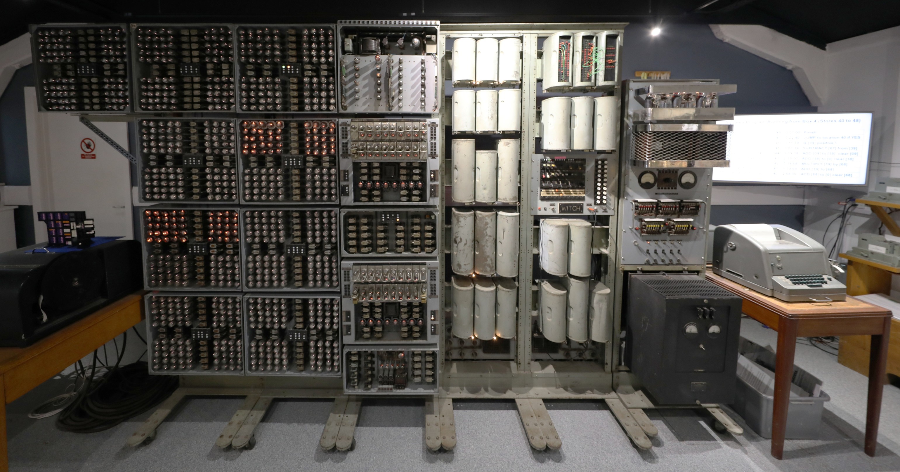
In 2023, to get inspiration I visited the WITCH computer in the National Museum of Computing, near Bletchley Park, which is comprised of hundreds of dekatrons. The people working there have managed to get the machine running, which I think is an incredible feat. They do a daily demonstration.
In July 2024, I got the opportunity to buy a couple of 12 step dekatrons (GS12C), about which I didn't hesitate a second. I had no clue what I was going to use these for, but I knew I needed them urgently. They had been laying around for a couple of months until the idea to use them in a digital clock gradually matured.
Figure 11 The Witch in Bletchley Park museum of computing
In my previous projects, I had been using dekatrons only as display devices. I did not use them for their original purpose: as counting (up/down) device. That was because all the "counting" was done in a microcontroller and the microcontroller directed the dekatron. This bothered me for a while. I wanted to do something where the dekatron was used for its original purpose, to count things and not be subordinate to a microcontroller.
I did some experimenting on how to couple the 'carry' on the output of one dekatron to the input of the next dekatron. Two document showed how to do this: the Sylvania brochure Decade Counter Tubes second edition and the Ericsson book Electronic Counting Circuits by J.B. Dance (chapter 4). but of course, the circuits were intended for different types of dekatrons, for different types of triodes and for different supply voltages then I intended to use. So I had to do a lot of experiments before I got it right. Luckily, the documents described very well the intended time-shifted waveforms on the two guide electrodes G1 and G2. So I could measure the waveforms on the oscilloscope and choose component values that gave the intended waveforms.
I took the idea from Sylvania to connect G1 through resistor-and-capacitor-parallel and G2 through an RC-filter-network, as illustrated in Figure 12.
Figure 12. Excerpt from Sylvania document
In the Ericsson document, they use a different RC topology, see Figure 13:
Figure 13. Excerpt from Ericsson document
I found out that dc-coupling the cathode of a dekatron to the grid of the triode means that the triode is conducting for a longer duration, which means that the power consumption is relatively large. This also leads to the necessity of a high-watt anode resistor. This can all be avoided by introducing a small capacitor between dekatron-cathode and triode-grid, which has the effect that only a brief pulse is given to the triode.But this technique cannot be applied for driving the nixies. So in the end I used both AC-coupling and DC coupling.
In chapter 4.4.9 of the Ericsson document, it is described how to drive nixie tubes (Ericsson calls them Digitrons) from a dekatron. Unfortunatly, the use a GCA10G type of dekatron for this puropose, which has 10 auxiliary anodes, that can be directly tied to the figures of the nixie tube. So I had to design a way to solve this for a normal dekatron. That proved to be quite easy, it only requires a lot of triodes: 10 triodes for one digit.
I found out the existence of the E90CC double triode tube, a tube specially intended for digital purposes. Fun fact about the E90CC that it clearly states in the datasheet that this tube is 100% useless for audio applications, because of microphony and hum. I really like this, because it means that not all of them have been taken by the audiophiles. I found someone in The Netherlands that would supply me with the desired quantities of tubes and sockets at a low price. In fact, the tubes cost no more than the sockets.
I decided to publish the on-going project on Hackaday.io and submit it to their 1Hz challenge. This meant to speed up the process. I went on to create an aluminium base plate, which was a large amount of work, given the tools that I have at hand. Some woodwork, find transformers for the power supply. Enfin, you can read this all in the project log.
Yesterday I finished putting all the tube sockets and I placed some of the tubes, just to see if everything fits nicely. Sure it does!
I have also a beefy transformer for the filaments of the double triodes and rectifier tubes for the power supply. The dekatrons and nixie tubes don't have a filament but the double triodes do!
Yesterday and today I worked on a wooden base plate, to put everything on including the heavy transformers. I glued three pieces of wood together, cut it and painted it. The aluminium base plate will sit on the wood using a hinge mechanism, so that it is easy to inspect the back where all the soldering should take place.
I soldered the rectifier circuit with EY88's. so I now have something like 200V and 400V. The EY's and all other tubes that a filament voltage of 6.3V will be connected in chains of 4, connected to 25.2V. Or something in that neighbourhood.
I preliminarily connected the nixie tubes so that display something (it's currently 12:06 all day). I started wiring the first dekatron circuit. It gives a sign of life but it isn't spinning yet.
Mixed day. After I blew up my function generator two weeks ago, by applying 300V to its output, today the magic smoke escaped for no reason from my 450V home built power supply. My indestructible 300V Delta Zierikzee power supply unfortunately just doesn't give enough for the Dekatrons to fire up. thankfully I found yet another home grown power supply in the attic, up to 400V.
This helped me to find one problem why the Dekatron wasn't spinning on first try. It appeared that for some reason, a large DC component appeared on the gates of the dekatron, where I would expect only 50 ~ 100V AC, phase shifted between G1 and G2. I still haven't pinpointed the cause, but I solved the problem by adding a 390nF capacitor, blocking whatever DC component there is.
Had it working. Then it stopped working again. This turned out to be a loose solder joint with one of the pins of the dekatron. With that solved, I have a spinner. Next stage is to get the output signal from the spinning dekatron. That should be 10Hz, to be inverted by one of the triodes and fed to the second dekatron, which should churn out the desirable 1Hz.
Major milestone: I've got the 1 Hz working. Mains frequency is given to the rightmost dekatron, which spins with 50 steps per second, that gives 5 full rotations per second. The outputs from states '0' and '5' are taken, inverted by an E90CC triode. This gives a 10Hz pulse train, which is given to the second dekatron, which makes 10 steps per second and therefore one full rotation in a second. See the attached movie in the files section.
I was working on the part of the circuit that deals with the tens of minutes. I had the dekatron wired up. Every time it gets an impulse, it should jumps to the next stage. I have used a GS12C, which has 12 stages. I have connected stage 6 to stage 0, stage 7 to stage 1, etc, thereby halving the number of outputs to 6, which is good, because it's the tens of minutes and after 5 it is supposed to go back to 0. So we will count 58, 59, 00, 01...
The particular problem I had is that the dekatron stepped through the stages, but got stuck on 0. It would not move from 0 to 1. I checked all solder joints, resistors etc. but didn't find a problem. The dekatron's inputs are two guides, G1 and G2, which are supposed to get an impulse, briefly shifted in time after one another. If you give an impulse to G1 and then to G2, it moves one stage up. You can also reverse the effect, by giving an impulse first to guide G2 and the to G1, which will cause the dekatron to move one stage down.
As an experiment, I reversed G1 an G2 and the dekatron started to move in the reverse direction and - a little to my surprise - did not get stuck anywhere. So for now, I think I will leave it this way. I have not connected the nixie tube yet; in this case I consider it an advantage, because I will have to reverse the nixie wiring to compensate for the reverse dekatron.
It looks a little like cogwheels now, like in a mechanical clock. Instead of looking at this as a problem, I might see this as a feature. I'll have to reverse some of the other dekatrons also, I guess.
No, not tubeless or voltless, just one tube less and one volt less...
The filaments of the rectifier tubes and triodes consume a lot of power. In total, 70W. In my transformer drawer I found a big transformer, with secondary taps of 23V, 24V and 25V. Therefore, I decided to work with strings of 4 tubes in series. Being all E-series tubes, 4 x 6,3V = 25.2V would fit well enough with the 25V output of the transformer. So, 4 strings of 4 E90CC's and one string of 4 EY88's. Although I needed only 3 EY88's in my design, I added one extra, doing nothing, just hanging around in the corner as a dropper tube.
While gradually realizing the No-Si Clock, I realized that I would need some kind of mechanism to set the time initially. I came up with a switch with three positions: one normal position, one position in which the minutes tick swiftly by and one position in which the hours pass by. But where am I going to put the switch? then I remembered the useless extra EY88. If I could do without that tube, I would have a place to put the switch. The solution I ended up with is to use not EY88's, but PY88's. These were used in series configuration, directly connected to mains voltage in tv sets of the day. They officially require 26V filament voltage each, so instead of stringing them in series, I could just use 3 of those, connected in parallel to the transformer's 25V. They will also work on a volt less.
Now I have room for my switch and additional advantage: the power consumption drops by almost 10W (6,.3V×1.55A).
Figure 14. The time adjust knob sits where a useless EY88 used to sit. You can see remaining three PY88 rectifier diodes. The switch on the far right may be the one I am going to use.
The No-Silicon Digital clock is ready! It is working correctly now. You can set the minutes by turning the "time adjust" knob counterclockwise and adjust the hours by turning it clockwise.
It consumes a little over 80W (mainly consumed by the filaments) and keeps the room nice and warm.
Presented the No-Si Digital Clock to the members of the family. Wife and kids (age 20+) were quite amused, I think they even liked it. My son wanted to know exactly the rotation time of each dekatron.
The clock is standing in the living room next to the tv now. We'll see how annoying the continuously spinning dekatrons are when viewing tv. Especially the very first one, rotating five times per second.
I think I will leave it there for a week or so and then it'll go into storage. Just to get it out sometimes to impress friends and family.
Yesterday, I noticed a problem with the No-Si digital clock. The hours figure show something unreadable. On closer inspection, it looked like the '5' was always burning regardless of the actual hour, through the intended figure. I thought a possible cause might be the triode tube, so I exchanged the responsible E90CC with another one in the clock. Bingo, now the '3' was constantly burning. So yes, the tube was the cause. Luckily, I have some spares laying around, so I put in another E90CC and the problem was solved.
I noticed that the dekatron that is counting the tens of minutes sometimes seems to miss a step. It seems to be getting worse when the clock is left on for a longer period of time (several hours). I guess I will have to look into that. I remember that this particular tube has shown some problems before, when I was building. Because it appeared to have a problem in a certain step, I decided back then to have it run in the opposite direction, e.g. counterclockwise in stead of clockwise. Which is kind of strange for a clock, admittedly. But it is as easy as swapping the G1 and G2 connections.
I have already tried to change the triode that is driving it, but that doesn't solve the problem. So the problem is either in the resistors and capacitors generating the phase shift G1/G2, or it is in the GS12C itself. I still have one or two of these lying around, but still it is a lot of work, because this particular tube does not sit in a socket, but the wires are soldered straight on. Maybe it's best to start with some measurements of the G1/G2 waveforms and then some tweaking.
Bring your design to life with the Elektor PCB Service, powered by Eurocircuits. Upload the project files and order professionally manufactured PCBs or assembled boards through a proven European production platform.
Supporting KiCad, Eagle, Gerber, and ODB++ formats, the service is suitable for everything from prototypes and validation builds to series production and volume manufacturing.
Veuillez saisir votre adresse électronique. Les instructions de réinitialisation de votre mot de passe vous seront immédiatement envoyées par courriel.
Elektor Magazine est depuis 65 ans l’une des principales sources d’information en électronique pour les ingénieurs, les concepteurs, les start-ups et les entreprises. Notre magazine est soutenu par une communauté active d’ingénieurs en électronique – des étudiants aux professionnels – passionnés par la conception et le partage d’idées innovantes.
Pour eux, nous publions chaque année des centaines de contenus sous différents formats, tels que des articles, des vidéos, des webinaires et d’autres formats d’apprentissage. Notre mission est de partager les connaissances de toutes les manières possibles et d’inspirer les lecteurs avec les dernières évolutions du secteur de l’ingénierie électrique.
Thank you for your vote!
Ajoutez vos commentaires
Thank you for your vote!
Veuillez vous connecter pour ajouter une note ou fermez pour revenir en arrière


Discussion (5 commentaire(s))