
Radio-Controlled Clock
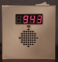
This alarm clock is controlled by the RTC described in another project, which ensures automatic time setting. The display adjusts according to ambient light, ensuring glare-free readability day and night.
Specifications
Elektor regularly publishes alarm clocks and other clocks, each more original than the last. The design described in this article isn't particularly original, but it's very functional, simple to build, easy to use, and pleasant to operate.
Since my first alarm clock, built in 1977 and still working, I've maintained largely the same specifications:
- The alarm clock must be readable at night. The display must therefore be either a backlit LCD or an LED;
- It must be readable during the day, but not too bright at night. This requires adjusting the display brightness to the ambient light. This is easy to achieve with a current-controlled 7-segment LED display. This is the solution I chose;
- It must be able to control a bedside lamp. Besides saving on a power outlet, turning on the lamp is a particularly effective way to wake up!
Four other features complete these specifications:
- A three-tone gong alarm is triggered upon waking, either as a single gong or repeatedly. Essential for heavy sleepers! The gong signal is generated by the microcontroller and transmitted to a small amplifier via the 8-bit DAC integrated into the microcontroller.
- All these settings are saved in case of a power outage;
- Designed for a deaf person, a 9V output is provided to power a powerful vibrator intended to shake the sleeper, literally and figuratively;
- Finally, the time setting is automatic. No more chores like setting all the alarm clocks in the house to summer or winter time, or adjusting them after a power outage.
Faced with the many ways to receive a clock signal, I chose the principle of a centralized clock powering the house via a wireless connection based on a signal transmitted at a frequency of 433 MHz. This clock is described in another project. The main advantages of this approach are that the small transmitter and receiver modules are readily available online at a very low cost, their implementation is quite simple, and their size is small, which is certainly a plus!
To meet these requirements, the use of a microcontroller is essential, and the one chosen is from Microchip's PIC family. The PIC 16F1765 is powerful enough for the task and is readily available online. It can be programmed with tools like PICKIT 3, which is also available at a low cost online.
The schematic
The schematic is divided into two parts: the control board and the HMI board.
The driver board is centered around the microcontroller, which is driven by its internal clock.
- At the very top of the diagram is the connector to the HMI board.
- At the top and slightly to the right is the connector for programming the microcontroller.
- At the top and right, a power MOSFET drives the vibrator.
- In the middle and slightly to the right, the current generator is based on an LM317 regulator whose output voltage is adjusted by two potentiometers accompanying an LDR. P1 determines the maximum display brightness. P2 adjusts the minimum brightness. However, the two settings are not completely independent. The simplest approach is to set P2 to its maximum value and adjust P1 for daytime brightness, then return to P2 to adjust nighttime brightness after covering the LDR. A short iteration between these two settings allows you to find the correct balance. The voltage-to-current conversion is handled by the segment resistors located on the HMI board.
- In the middle and on the far right is the amplifier module, which transmits the gong signal generated by the microcontroller's DAC to a small speaker.
- At the bottom is the alarm clock's power supply, provided by a small 9V block that powers the display's current generator, the vibrator, and a standard 5V regulator for the rest of the electronics.
- Finally, an optotriac drives the triac that controls the mains socket. This triac is bypassed by a switch, allowing manual activation of the socket.
- At the top left is the 433 MHz receiver, which transmits the time signal to the microcontroller. It is essential to choose a superheterodyne receiver module. The least expensive modules are based on a superregenerative receiver, but I have never been able to get them to work reliably, a finding consistent with the negative reviews found online. With the model I selected, the range is about fifteen meters, including walls and floors. The small solenoid antennas supplied with the modules prove sufficient for the purpose.
All of this is more complicated to explain than to illustrate on the diagram!
The HMI board is controlled by an SPI bus. Two 74HCT4094 serial-parallel converters, connected in cascade, transmit commands from the microcontroller to the 4-digit, 7-segment display and the four-button "keypad." Transistors surrounding the display control it.
Implementation
These two boards are built on two main printed circuit boards. As I prefer to make my own PCBs, they are single-sided. There are three jumpers on the driver board.
The HMI board uses surface-mount components. For passive components, I used 0805 size solder, which is still solderable even without special skills, provided you use a fine-tipped soldering iron and small-diameter solder. With a little patience, it's doable, and I've made about ten boards without much difficulty.
Two small printed circuit boards house three alarm time setting buttons and alarm settings on one, and two parallel buttons activated by a large alarm stop button on the other.
The entire assembly is housed in a 3D-printed enclosure.
The user manual for this alarm clock is attached. It is written in french.
The Software
The program is written in assembly language. I have attempted to document the program, while being aware that machine language does not make it easy to read. However, the program remains quite short, 1500 words, of which 900 are the program code itself, with the remainder dedicated to the sound generation tables. It was written using version 8.35 of MPLAB, the last version to support MPASM assembler. A conversion to the current MPLAB assembler is not very complicated, but somewhat laborious to implement and much less readable.
The most complex part of the program, although executed in a very conventional manner, concerns the generation of the alarm sound. The microcontroller has an 8-bit DAC, which handles this generation.
The gong is timed by timer 2, which generates an interrupt every 100 µs. This interrupt increments a 16-bit global counter, an index to the sound generation.
The sound consists of three notes, with frequencies of 440, 550, and 660 Hz. The amplitude of these notes varies over time, starting with a rapid increase in intensity followed by a slow decrease. These notes are staggered over time. The starting time of each note is determined by the correct value of the index.
For each note, a 16-bit counter, incremented by a step adapted to the frequency, leads, upon overflowing, to the reading of the amplitudes of the sine wave and the envelope, each encoded on 4 bits. Simply multiplying the two values yields the amplitude of the 8-bit note. This multiplication is achieved by scanning a 256-byte table. The three notes are added together, the sum is reduced to 8 bits, and written to the converter.
Reading the time signal sent by the 433 MHz transmitter is also handled by the interrupt subroutine. The encoding principle is described in the RTC clock generator project. The reading process involves waiting for the generation of a message that begins with a stable level 1 of approximately fifteen milliseconds, then reading the time interval between two falling edges (which have a steeper slope than the rising edges) of the receiver. This interval value determines the message encoding. To do this, timer 1 is read at each interrupt generated by a falling edge of the 433 MHz receiver. The time interval is obtained by subtracting readings N-1 and N, which allows the counter to resynchronize with the signal.
A window discriminator ensures accurate analysis of this interval and error handling in case of overflow or underflow.
The message encoding consists of three bytes representing the hour and minute, both in BCD, and a checksum.
The program's main loop handles:
- Reading the time every minute. The microcontroller's internal clock accuracy, on the order of 1%, is insufficient for accurate clocking. Therefore, it must constantly resynchronize with the time signal sent by the time server;
- Managing the alarm time;
- Managing the keypad;
- Executing commands.
The alarm time and all other parameters are stored in the EEPROM and are therefore always valid in case of a power outage.
Conclusion
The intended user of this alarm clock is far from being a technician. He is delighted by the simplicity of this alarm clock, and in particular, the automatic time setting is a real joy for him, as power outages are not so rare after all!
Want to build a project?
Bring your design to life with the Elektor PCB Service, powered by Eurocircuits. Upload the project files and order professionally manufactured PCBs or assembled boards through a proven European production platform.
Supporting KiCad, Eagle, Gerber, and ODB++ formats, the service is suitable for everything from prototypes and validation builds to series production and volume manufacturing.
Made in Europe. Fast. Reliable. Professional.
Discussion (1 commentaire(s))