
Radio-Controlled FM Alarm Clock
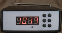
This alarm clock is controlled by the real time clock system described in another project, ensuring automatic time setting. The display adjusts to ambient light, guaranteeing glare-free readability day and night. The radio receives FM signals. Four stations can be preset.
The specifications
Elektor regularly publishes alarm clocks and other clocks, each more original than the last. The design described in this article isn't particularly original, but it's very functional, simple to build and use, and pleasant to operate.
Since my first alarm clock, built in 1977 and still working, I've maintained largely the same specifications:
- The alarm clock must be readable at night. The display must therefore be either a backlit LCD or an LED;
- It must be readable during the day, but not too bright at night. This requires adjusting the display brightness to the ambient light. This is easy to achieve with a current-controlled 7-segment LED display. This is the solution I chose;
- It must be able to control a bedside lamp. Besides saving on a power outlet, turning on the lamp is a particularly effective way to wake up!
Three other features complete these specifications:
- A small FM module provides the alarm sound function. Of course, the radio can be activated independently of the alarm function. This module is controlled by a few buttons that allow:
o Scanning to higher or lower frequencies, stopping at found stations,
o As well as saving four stations.
- All these settings are saved in case of a power outage;
- Finally, the time is set automatically. No more chore of resetting all the alarm clocks in the house to summer or winter time, or adjusting them after a power cut.
Faced with the multiple ways of receiving a clock signal, I chose the principle of a centralized clock that powers the house via a wireless connection based on a signal transmitted on the 433 MHz frequency. This clock is described in another project. The main advantages of this approach are that the small transmitter and receiver modules are readily available online at a very low cost, their implementation is quite simple, and their size is minimal, which is certainly a plus!
To meet these requirements, the use of a microcontroller is essential, and the one chosen is from Microchip's PIC family. The PIC 16F1765 is powerful enough for the task and is readily available online. It can be programmed with tools like the inexpensive PICKIT 3, also available online. It has specialized pins, such as the one that directly powers the radio module (100mA max), which simplifies the process.
The schematic
The schematic is divided into two parts: the driver board and the HMI board.
The driver board is centered around the microcontroller, which is driven by its internal clock. A 32 kHz watch crystal beats the timer 1, which controls the time.
- At the top center of the schematic is the connector to the HMI board.
- At the top left is the connector for programming the microcontroller.
- In the middle, slightly to the right, the current generator is based on an LM317 regulator whose output voltage is adjusted by two potentiometers accompanying an LDR (Light Dependent Resistor). P1 determines the maximum display brightness. P2 adjusts the minimum brightness. However, the two settings are not completely independent. The simplest approach is to set P2 to its maximum value and adjust P1 for daytime brightness, then return to P2 to adjust nighttime brightness after covering the LDR. Iterating between these two settings allows you to find the right balance, which can be a bit tricky. Using a low dropout regulator such as the LT1086 would probably make this adjustment easier. The voltage-to-current conversion is handled by the resistors at the base of the segments positioned on the HMI board.
- In the middle and on the far right are the RDA 5807 FM radio modules and a Class D amplifier based on a PAM 8302, which drives a small speaker. These modules are readily available online at low prices. A DAB+ module is not yet planned, as these are rare and still very expensive.
- In the middle and on the left is the alarm clock's power supply, provided by a small 5V block that powers the display's current generator and the amplifier, as well as a standard 3.3V regulator for the rest of the electronics. The 3.3V supply is determined by the FM receiver.
- Finally, an optotriac drives the triac that controls the mains power outlet. This triac is bypassed by a switch, allowing manual activation of the outlet.
- At the top left is the 433 MHz receiver, responsible for transmitting the time signal to the microcontroller. It is essential to choose a superheterodyne receiver module. The least expensive modules are based on a superregenerative receiver, but I have never been able to get them to work reliably, a finding consistent with the negative reviews found online. With the chosen model, the range is about fifteen meters, including walls and floors. The small solenoid antennas supplied with the modules prove sufficient for this purpose.
All of this is more complicated to explain than to illustrate on the schematic!
The radio module and the HMI board are controlled by an I2C bus. Two standard PCF8574 chips transmit commands from the microcontroller to the 7-segment, 4-digit display and to the simplified eight-key keypad. Transistors surrounding the display provide its current control.
Construction
Two main printed circuit boards (PCBs) make up these two boards. Since I prefer homemade PCBs, they are single-sided.
The HMI board uses surface-mount components (SMD). For the passive components, I used 0805 size components, which are still solderable without being particularly skilled, provided you use a fine-tipped soldering iron and small-diameter solder. With a little patience, it's doable, and I made about ten boards without much difficulty.
The entire assembly is housed in a Hamond case, model 1598BBK.
The user manual for this alarm clock is attached.
The Software
The program is written in C, using the MPLAB IDE.
The program's primary function is time and display management. Timer 1, driven by a 32 kHz crystal, generates an interrupt every 4 ms. The interrupt program performs three functions:
- Increment the time (hour, minute, and second),
- Refresh the display,
- Manage the keyboard.
The second primary function is reading the time signal sent by the 433 MHz transmitter. The encoding principle is described in the RTC clock generator project. Reading the signal involves waiting for the generation of a message that begins with a pause of approximately fifteen milliseconds, then reading the time interval between two falling edges (which have a steeper slope than rising edges). This interval value determines the message encoding. To do this, Timer 3 is read at each falling edge of the 433 MHz receiver. The time interval is obtained by subtracting readings N-1 and N, allowing the counter to resynchronize with the signal.
A window discriminator ensures accurate analysis of this interval and handles errors in case of overflow or underflow.
The message encoding consists of three bytes representing the hour and minute, both in BCD, and a checksum.
The third major function manages the radio module and is handled by a series of subroutines.
Finally, several subroutines manage the I2C bus, writing a character or a string of characters.
The program's main loop handles:
- Reading the time at 4:00 AM, unless the time signal has not been received, in which case a reading is taken every hour;
- Managing the wake-up time;
- Managing the keyboard;
- Executing commands.
The four preset stations, the alarm time, the alarm activation status, and all other settings are saved to the EEPROM each time they are changed. Therefore, they are restored to their original state after a power outage.
Conclusion
Four of these clock radios are installed in my home. They work perfectly. The time is legible in all lighting conditions, without glare in the dark, and the automatic time setting function is a real plus, as power outages are not uncommon!
Want to build a project?
Bring your design to life with the Elektor PCB Service, powered by Eurocircuits. Upload the project files and order professionally manufactured PCBs or assembled boards through a proven European production platform.
Supporting KiCad, Eagle, Gerber, and ODB++ formats, the service is suitable for everything from prototypes and validation builds to series production and volume manufacturing.
Made in Europe. Fast. Reliable. Professional.
Discussion (4 commentaire(s))