
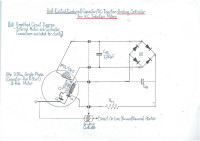
NOVEL Self-Excited Capacitor/DC-Injection Braking Control for an AC Motor.
Faced with an empty Lathe motor-control cabinet and needing to construct a D.O.L. Forward/Reverse, N.V. Release starter, why not add Electric Braking?
The Genesis of my Project...
Like all good yarns, it's a long story..........!
I purchased my WEY YII TY-1000 x 330 metal-cutting Lathe 2nd hand from an idiot. This guy was electrically ignorant (read: suicidal!) beyond belief. There is insufficient space to give you the laundry-list of electrical safety "NO-NO's" this half-wit perpetrated but just to give you a hint: how about wiring a 2.2Kw single-phase motor through a micro-switch? ...You get the picture!
The lathe was bought for its mechanical condition which was generally very good but with the certain knowledge that a new controller had to be constructed. Since I was starting with what was, effectively, the proverbial 'blank sheet of paper' it required little extra effort to incorporate an electric-braking facilty into the Forward/Reverse D.O.L. starter which I deemed a desirable feature that would improve my machining productivity.
From the outset I settled on one firm rule I would adhere to rigidly: I would use no active semiconductor device more complex than a Diode, Yep', real ancient electromagnetic Power "Electronics"!
The design commenced with a great deal of documentary technical research leading to an initial experimental lash-up of an externally-excited D.C. Injection-Braking prototype board which demonstrated quite powerful braking - 2.2 seconds (max) - but suffered from the disadvantage of requiring a bulky and expensive transformer and the nagging fact of knowing that this performance fell far short of optimal braking (more on this later).
After further research and chance discovery I quickly became acquainted with the intriguing and most attractive possibilities offered by a self-excited electric-braking facilty. You could say at this point it got me very 'externally excited' (excuse the pun)!
Before proceeding to the more prosaic parts of this narrative, the reader is requested to peruse and familiarise themselves with the following documentation which are essential to understanding the relevant techniques and how this relates to my project:-
A technical overview published in the I.J.E.I.T., V1 Issue 6, June 2012:-
https://pdfs.semanticscholar.org/bd12/9fa0a76a2e98bbdbb4bee93b67f02b61659d.pdf
.....and,
Royce E. Johnson's most important 1957 U.S. Patent # 2,818,539:
https://www.google.com/patents/US2818539
........ and this, directly relevant to single-phase motors, U.S. Patent # 2,922,097:
https://www.google.com/patents/US2922097
https://www.google.com/patents/US2922097
Assuming you have now grasped the intent of my design direction it is worthwhile my summation of the essential character of the combined electric-braking techniques for those readers unfamiliar with the two principle techniques employed and in order to understand their intimate interaction when implemented.
Regenerative (i.e. "Capacitor") Braking offers significant braking only in the initial portion of the braking cycle when the rotor first begins to decelerate but quickly tapers off as the shaft speed falls away leaving only mechanical bearing and rotor windage-friction to bring the rotor to a final halt. This effect is only achievable wiith large amounts of capacitance of no less amount than that required at resonance, the point of maximum energy-transfer (i.e. when the motor is operating as alternator) whilst D.C. Injection-Braking produces a powerful braking effect only in the final, terminal phase of the braking cycle as the rotor approaches its zero-speed, stop-point due to the high, 'blocking' impedance of the "RUN" winding at the start of the braking cycle which rapidly tapers off concordantly with rotor deceleration allowing progressively more D.C. excitation current to flow. This assumes that one is using a fixed voltage unregulated power supply. To 'push' the braking-ffect of D.C. Injection Braking further up the braking cycle would require the additional (and for the majority of applications, unnecessary) complication of a variable-voltage, automatic ramp-up power supply.
Applied singularly, neither technique results in an optimal braking effect but synergistically combined, produces powerful and consistent electrodynamic braking of the rotor across the entire deceleration speed curve with seamless transition in braking torque between the two methods as the stopping action proceeds to a full-STOP.
Ah-hh, the "GoldiLocks" solution, Nirvana!
A good and sound reason to become 'self-excited' (excuse the pun)!
.......But what finally "sold" me on this combined-technique approach was Royce Johnson's practical experimental prototype and the braking results he describes in his patent (unusual to be reported in a patent). I didn't need much more convincing although the one major, and significant departure in my intended application was that the subject motor was a rather large 3Hp (2.2Kw) single-phase (Capacitor-Run/Start) A.C. Induction motor which will result in some equally significant divergence of design detail in terms of circuit arrangement and implementation.
The decision is made: Self-Excited, Combined Regenerative/D.C. Injection-Braking it is!
So, on to the circuit design. No secret here, it's plastered all over the introductory lab front-window, so you've already given it the once-over.
Probably appropriate to firstly acquaint you with the symbology:-
On the face of it the circuit diagram appears a beguilingly simple, almost naive, perhaps even primitive linear power supply but don't let this fool you; its crude look belies some very complex and powerful electrodynamic interactions occurring under braking. The "RUN" winding output waveform takes the form of a 'spiky' damped oscillation and under many and varied rotational inertias/spindle-speeds there is much 'slewing' and distortion - real 'wild' ride!
The D.C. output from the Bridge Rectifier is likely to be distorted so in order to maximise the power transfer are there any passive devices/techniques I can apply to 'condition' this outout waveform and improve its form factor?
I am unsure about the inclusion of Cᵣₛ (shown in dashed outline) for smoothing, after all the rather large inductance of the "START" winding emulates a natural choke so should produce some smoothing. Of course, in a conventional transformer powered linear power supply inclusion of smoothing capacitance is taken as a mandatory "given".
So I want to hear from experienced motor control designers and others who can advise me on these points. ....what parameters/selection criteria and calculation methods should I use to optimise these components and determine their value?
And, the brake-torque limiting resistor Rₜₗ, - how should I determine its resistance value and appropriate power rating for this type of application, if needed at all?
Answers please....
.... and any other useful suggestions are welcomed ...if possible, accompanied by diagrams and other useful references and web-links.
My Seemingly Elusive Goal: Idea ==> Build..... I need your urgent HELP!
I am anxious and eager to proceed to building my prototpe self-excited combination electric-brake (the sooner built, the sooner I can report my results) but am unable to make any progress due to the prohibitive cost of the necessarily large caoacitance - 1250µF. However, it occurs to me that there is a great deal of surplus componentry lying around: - left-overs from commercial jobs/obsolete spares, etc that would otherwise go to waste or else salvaged components from de-comissioned electrical plant and contol cabinets, e.g. power-factor correction racks, indusrial welding-machines, etc. passing through the scrap recyclers, probably heading for land-fill in some third-world country(!)
What a waste! I could use this, unfortunately I live in NEW ZEALAND - a long way from the waste 'gold-mines' of the larger industrialised countries of Europe. By comparison, NZ has only a miniscule industrial base so as you can imagine my elusive capacitors are pretty thin on the ground i.e. non-existant. So, I would like to appeal to the ELEKTOR community of 'projecteers' and makers to ask if they can assist intracking-down a readily available source of supply of these unwanted capacitors. Perhaps you are a factory electrician, a motor control engineer or installer, you work in a recycling facility or you know friends who do, pass my request along, let them know.....
As 1250µF of cpacitance is a fairly large value it is likely to have to be made-up from multiples of smaller values, i.e. 4 x 300µF, 6 x 200µF, 12 x 100µF, etc. I am given to believe that the largest module-size typically available is about 400µF, the larger the better in order to keep the component head-count low but I'll take whatever i can get. The working voltage needs to be >400VAC. Electrolytic types are NOT acceptable for this application only MPPF types (Metallised PolyPropylene Film) are suitable (see sample attachment picture). To help in your search the type of manufacturer names are the likes of ELECTRONICON Kondensatoren GmbH, EXXALIA Technologies, Vossloh-Schwabe GmbH General Electric. Check with me first to compare model numbers.
If these are salvaged they must have no weather exposure and I'll probably need an additional few in case any of them are duds, also keep the terminal caps/connectors.
If you can help, get in touch with me at: pyralog@yahoo.co.nz
Also, while searching around, I'm also in need of various pieces of industrial switch-gear. So if you can help out on these, then also drop me a line (e-mail, as above).
i am intending to write a descriptive artricle on electric-braking techniques and would like to canvass the readership to see if anyone can find for me the earliest known patent for the regenerative, solid-state half-wave rectifier braking system shown in the accompanying diagram (see first attachment) as I wish to authoritatively quote this reference. Perhaps someone who knows their way around the patent system better than I may be able to help. Again let me know (e-mail address, above).
In a distantly related way, I would also like to hear from anyone who works with deep-well submersible pumps - long story - I'll let you know!
Finally, a shout-out to my fellow metal-bashing machinists - drop me a line and say "Hi"!, I'd like to hear from you......
e-mail: pyralog@yahoo.co.nz
Like all good yarns, it's a long story..........!
I purchased my WEY YII TY-1000 x 330 metal-cutting Lathe 2nd hand from an idiot. This guy was electrically ignorant (read: suicidal!) beyond belief. There is insufficient space to give you the laundry-list of electrical safety "NO-NO's" this half-wit perpetrated but just to give you a hint: how about wiring a 2.2Kw single-phase motor through a micro-switch? ...You get the picture!
The lathe was bought for its mechanical condition which was generally very good but with the certain knowledge that a new controller had to be constructed. Since I was starting with what was, effectively, the proverbial 'blank sheet of paper' it required little extra effort to incorporate an electric-braking facilty into the Forward/Reverse D.O.L. starter which I deemed a desirable feature that would improve my machining productivity.
From the outset I settled on one firm rule I would adhere to rigidly: I would use no active semiconductor device more complex than a Diode, Yep', real ancient electromagnetic Power "Electronics"!
The design commenced with a great deal of documentary technical research leading to an initial experimental lash-up of an externally-excited D.C. Injection-Braking prototype board which demonstrated quite powerful braking - 2.2 seconds (max) - but suffered from the disadvantage of requiring a bulky and expensive transformer and the nagging fact of knowing that this performance fell far short of optimal braking (more on this later).
After further research and chance discovery I quickly became acquainted with the intriguing and most attractive possibilities offered by a self-excited electric-braking facilty. You could say at this point it got me very 'externally excited' (excuse the pun)!
Before proceeding to the more prosaic parts of this narrative, the reader is requested to peruse and familiarise themselves with the following documentation which are essential to understanding the relevant techniques and how this relates to my project:-
A technical overview published in the I.J.E.I.T., V1 Issue 6, June 2012:-
https://pdfs.semanticscholar.org/bd12/9fa0a76a2e98bbdbb4bee93b67f02b61659d.pdf
.....and,
Royce E. Johnson's most important 1957 U.S. Patent # 2,818,539:
https://www.google.com/patents/US2818539
........ and this, directly relevant to single-phase motors, U.S. Patent # 2,922,097:
https://www.google.com/patents/US2922097
https://www.google.com/patents/US2922097
Assuming you have now grasped the intent of my design direction it is worthwhile my summation of the essential character of the combined electric-braking techniques for those readers unfamiliar with the two principle techniques employed and in order to understand their intimate interaction when implemented.
Regenerative (i.e. "Capacitor") Braking offers significant braking only in the initial portion of the braking cycle when the rotor first begins to decelerate but quickly tapers off as the shaft speed falls away leaving only mechanical bearing and rotor windage-friction to bring the rotor to a final halt. This effect is only achievable wiith large amounts of capacitance of no less amount than that required at resonance, the point of maximum energy-transfer (i.e. when the motor is operating as alternator) whilst D.C. Injection-Braking produces a powerful braking effect only in the final, terminal phase of the braking cycle as the rotor approaches its zero-speed, stop-point due to the high, 'blocking' impedance of the "RUN" winding at the start of the braking cycle which rapidly tapers off concordantly with rotor deceleration allowing progressively more D.C. excitation current to flow. This assumes that one is using a fixed voltage unregulated power supply. To 'push' the braking-ffect of D.C. Injection Braking further up the braking cycle would require the additional (and for the majority of applications, unnecessary) complication of a variable-voltage, automatic ramp-up power supply.
Applied singularly, neither technique results in an optimal braking effect but synergistically combined, produces powerful and consistent electrodynamic braking of the rotor across the entire deceleration speed curve with seamless transition in braking torque between the two methods as the stopping action proceeds to a full-STOP.
Ah-hh, the "GoldiLocks" solution, Nirvana!
A good and sound reason to become 'self-excited' (excuse the pun)!
.......But what finally "sold" me on this combined-technique approach was Royce Johnson's practical experimental prototype and the braking results he describes in his patent (unusual to be reported in a patent). I didn't need much more convincing although the one major, and significant departure in my intended application was that the subject motor was a rather large 3Hp (2.2Kw) single-phase (Capacitor-Run/Start) A.C. Induction motor which will result in some equally significant divergence of design detail in terms of circuit arrangement and implementation.
The decision is made: Self-Excited, Combined Regenerative/D.C. Injection-Braking it is!
So, on to the circuit design. No secret here, it's plastered all over the introductory lab front-window, so you've already given it the once-over.
Probably appropriate to firstly acquaint you with the symbology:-
- Cₛ = "START" Capacitor
- Cᵣ = "RUN" Capacitor
- BR = Bridge Rectifier (Full-Wave)
- CᵣB = Regenerative Braking Capacitor
- Cᵣₛ = Reservoir Smoothing Capacitor
- Rₜₗ = Brake-Torque Limiting Reistor
- "START" Winding = 3.6Ω 35mH
- "RUN" Winding = 0.9Ω 10mH
On the face of it the circuit diagram appears a beguilingly simple, almost naive, perhaps even primitive linear power supply but don't let this fool you; its crude look belies some very complex and powerful electrodynamic interactions occurring under braking. The "RUN" winding output waveform takes the form of a 'spiky' damped oscillation and under many and varied rotational inertias/spindle-speeds there is much 'slewing' and distortion - real 'wild' ride!
The D.C. output from the Bridge Rectifier is likely to be distorted so in order to maximise the power transfer are there any passive devices/techniques I can apply to 'condition' this outout waveform and improve its form factor?
I am unsure about the inclusion of Cᵣₛ (shown in dashed outline) for smoothing, after all the rather large inductance of the "START" winding emulates a natural choke so should produce some smoothing. Of course, in a conventional transformer powered linear power supply inclusion of smoothing capacitance is taken as a mandatory "given".
So I want to hear from experienced motor control designers and others who can advise me on these points. ....what parameters/selection criteria and calculation methods should I use to optimise these components and determine their value?
And, the brake-torque limiting resistor Rₜₗ, - how should I determine its resistance value and appropriate power rating for this type of application, if needed at all?
Answers please....
.... and any other useful suggestions are welcomed ...if possible, accompanied by diagrams and other useful references and web-links.
My Seemingly Elusive Goal: Idea ==> Build..... I need your urgent HELP!
I am anxious and eager to proceed to building my prototpe self-excited combination electric-brake (the sooner built, the sooner I can report my results) but am unable to make any progress due to the prohibitive cost of the necessarily large caoacitance - 1250µF. However, it occurs to me that there is a great deal of surplus componentry lying around: - left-overs from commercial jobs/obsolete spares, etc that would otherwise go to waste or else salvaged components from de-comissioned electrical plant and contol cabinets, e.g. power-factor correction racks, indusrial welding-machines, etc. passing through the scrap recyclers, probably heading for land-fill in some third-world country(!)
What a waste! I could use this, unfortunately I live in NEW ZEALAND - a long way from the waste 'gold-mines' of the larger industrialised countries of Europe. By comparison, NZ has only a miniscule industrial base so as you can imagine my elusive capacitors are pretty thin on the ground i.e. non-existant. So, I would like to appeal to the ELEKTOR community of 'projecteers' and makers to ask if they can assist intracking-down a readily available source of supply of these unwanted capacitors. Perhaps you are a factory electrician, a motor control engineer or installer, you work in a recycling facility or you know friends who do, pass my request along, let them know.....
As 1250µF of cpacitance is a fairly large value it is likely to have to be made-up from multiples of smaller values, i.e. 4 x 300µF, 6 x 200µF, 12 x 100µF, etc. I am given to believe that the largest module-size typically available is about 400µF, the larger the better in order to keep the component head-count low but I'll take whatever i can get. The working voltage needs to be >400VAC. Electrolytic types are NOT acceptable for this application only MPPF types (Metallised PolyPropylene Film) are suitable (see sample attachment picture). To help in your search the type of manufacturer names are the likes of ELECTRONICON Kondensatoren GmbH, EXXALIA Technologies, Vossloh-Schwabe GmbH General Electric. Check with me first to compare model numbers.
If these are salvaged they must have no weather exposure and I'll probably need an additional few in case any of them are duds, also keep the terminal caps/connectors.
If you can help, get in touch with me at: pyralog@yahoo.co.nz
Also, while searching around, I'm also in need of various pieces of industrial switch-gear. So if you can help out on these, then also drop me a line (e-mail, as above).
i am intending to write a descriptive artricle on electric-braking techniques and would like to canvass the readership to see if anyone can find for me the earliest known patent for the regenerative, solid-state half-wave rectifier braking system shown in the accompanying diagram (see first attachment) as I wish to authoritatively quote this reference. Perhaps someone who knows their way around the patent system better than I may be able to help. Again let me know (e-mail address, above).
In a distantly related way, I would also like to hear from anyone who works with deep-well submersible pumps - long story - I'll let you know!
Finally, a shout-out to my fellow metal-bashing machinists - drop me a line and say "Hi"!, I'd like to hear from you......
e-mail: pyralog@yahoo.co.nz
Want to build a project?
Bring your design to life with the Elektor PCB Service, powered by Eurocircuits. Upload the project files and order professionally manufactured PCBs or assembled boards through a proven European production platform.
Supporting KiCad, Eagle, Gerber, and ODB++ formats, the service is suitable for everything from prototypes and validation builds to series production and volume manufacturing.
Made in Europe. Fast. Reliable. Professional.
Discussion (0 commentaire(s))