
Electrically Safe LED-to-Lamp Converter (140095)
Replace just about any low-current LED by a 100-watt incandescent bulb.
For loads up to 100 watts
Have you ever thought of amplifying LED light? Here we do it, with just about any low-current LED driving signal at the input and a 100-watt incandescent bulb as very bright “output device”.Compared to an ordinary lamp most traditional LEDs are weak when it comes to light emission. That’s okay for many purposes, but sometimes you want a big lamp instead of a measly LED.
This “light booster” as you might call it is used for switching a mains powered incandescent lamp on and off by means of a tiny LED in an opto-isolator available at the input of the circuit. This LED should take the place of the LED you want to “beef up” in terms of light emission. The opto-isolator affords the required electrical isolation between your precious driver circuit on the one side (microcontroller-based, RPi? ARM? Arduino?), and the lamp and lamp control circuit at the other side, the latter sitting dangerously at mains potential. The power of the lamp to be controlled should be in the range 15-100 watts.
Read on or read as PDF in your preferred language
Electrically Safe LED-to-Lamp ConverterLED-naar-lamp-interface
LED-nach-Glühlampe-Konverter
remplacer une LED par une lampe : convertisseur isolé
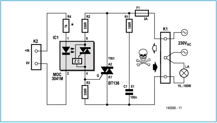
Schematic
The lamp gets controlled via a type MOC3041M “zero crossing opto isolator triac driver”, that’s IC1 in Figure 1 and [1] on the Internet. The combined opto receiver / zero crossing detector inside the MOC3041M is capable of driving a power triac directly — here the common BT136 triac is used. The MOC3041M, says the datasheets, consists of gallium arsenide infrared emitting diodes optically coupled to monolithic silicon detectors performing the function of Zero Voltage Crossing bilateral triac driver. They are designed for use with a triac in the interface of logic systems to equipment powered from 115/230-VAC single-phase AC powerlines, such as medium-power signal lamps, industrial controls, motors, solenoids, consumer appliances, etc.In our circuit the diode in IC1 gets forward biased by the driving circuit. As the diode conducts it emits infrared to the zero crossing detector circuit, which responds by supplying trigger pulses to the gate of triac TRI1. The triac allows the lamp connected on output connector K3 to light up and go off in a controlled fashion.
Snubber network R1-C1 (note X1-class cap there) provides a short term alternate current path around the triac device, ensuring the circuit discharges safer and quieter (in terms of electrical noise) when a (partly) inductive load is powered.
Fuse F1 protects the circuit against damage from overload conditions.
The value of resistor R4 is relatively high on purpose to allow input swings up to 15 V of the lamp on/off control voltage. It can be lowered using Ohm’s Law depending on the voltage and current requirement of the on/off pulse:
R = (VK2 – VF)/ IFT [Ω]
where IFT is the “rated LED Trigger Current” (datasheet: 15 mA) and VK2, the drive signal’s top level (usually 5 V or 3V3 from an I/O line). Do not exceed 6 volts reverse on the LEDs inside IC1. Some experimenting with R1 may be required to achieve optimum response to the current and voltage available to drive the LED you are replacing by the one in IC1.
Construction
First off, stark words of caution.Do not operate or work on the finished circuit at any time when it is not fully enclosed and secured in its isolating case. All requirements, recommendations and legislation relevant to electrical safety in your country, state or area apply.
The little circuit should be easy to build on a little circuit board. The 3-A fuse is inserted into a PCB-mount holder, preferably one with a safety cover. The triac does not require a heatsink and can be bolted down to the PCB surface. R1 is a power resistor and should be mounted a millimetre or two above the board surface to allow for its dissipated heat.
Testing Procedure
With safety in mind no testing should be done on the circuit unless it is either:1. fully encased so that 0—no—none—zilch—nada—zero parts can be touched;
2. powered via an approved isolating transformer.
Connect the 115/230-VAC supply to the converter via screw terminal block K1. Connect a 115/230 volts, 15-100 watts lamp to K3. Connect the LED control signal to connector K2; positive to + IN terminal, negative to 0 V. Inform your parents or housemates. Advice all to press control-S. Is the UPS ready? Apply AC line power. To switch on the lamp, take the drive signal on K2 High to +5-15 V (assuming R1 = 1 kΩ).
Component List
ResistorsDefault: 0.25W, 5%, 250V
R1 = 100Ω, 1W, 350V
R2,R3 = 330Ω
R4 = 1kΩ (see text)
Capacitor
C1 = 100nF 630V, X1 Class
Semiconductors
TRI1 = BT136
Miscellaneous
IC1 = MOC3041M
K1 = 3-way PCB screw terminal block, 650V, 7.68 mm pitch
K2 = 2-way PCB screw terminal block, 250V, 3.5 mm pitch
F1 = 3A slow blow (T)
Fuseholder, PCB mount, with cap
6-way DIL IC socket
Case, insulated, approved for mains use
Want to build a project?
Bring your design to life with the Elektor PCB Service, powered by Eurocircuits. Upload the project files and order professionally manufactured PCBs or assembled boards through a proven European production platform.
Supporting KiCad, Eagle, Gerber, and ODB++ formats, the service is suitable for everything from prototypes and validation builds to series production and volume manufacturing.
Made in Europe. Fast. Reliable. Professional.
Discussion (4 commentaire(s))