
Sound Blink - A unique DIY portable speaker
A portable speaker offering a ton of functions. 6 speaker drivers, wooden enclosure, WiFi LED equalizer, custom light patterns & much more...
This project which I named Sound blink is an effort to bring a difference to the normal portable speaker so that it’s not just a speaker but a bit more. This speaker is loaded with lots of functions and thus its very unique. I wanted to be this project very special to me I have so put my whole heart into it. Its also a fully hand build project and all the parts are made by modifying easily available materials. I wanted this project to be different but also a good looking one. All the components, design, techniques are pretty robust so that this speaker won't be having any issues in the near future. Achieving all the requirements was the biggest challenge for this project since I should come up with simple and effective techniques for each stage of build starting from which material to choose to the final stage of how would it look. Everything turned out good and I'm very glad to share this project.
Please watch the full build video first to have better idea about the project
FEATURES
1) 25W + 25W audio output
2) Onboard soft keys for audio controls ( play, next track, previous track, volume up, volume down)
1) wooden speaker enclosure for better sound performance.
2) It consists of 6 drivers (2 woofers, 2 tweeters & 2 passive radiators) for more clear and quality sound especially at higher volume levels without any distortion. Two way passive audio crossovers is used for this purpose.
4) The two passive radiators at top and bottom act like sub woofers and enhance the bass response.
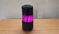
5) It consists of a WiFi controlled VU meter where the LED display is enclosed in an acrylic casing. Further, the light is controlled through a mobile app which enables 16 million color combination, default color patterns, custom color patterns, color detection through camera, group connect feature, internet control and much more.
6) The LED display could be also used as a mood light lamp.
7) It has four 18650 Li-ion batteries each of 5800mah arranged in 4S1P configuration. Thus making a total of 16.8V, 5800mah battery pack.
NOTE: the capacity that I mentioned is the factory specification and the actual capacity will be lesser than it.
8) It ensures safer charging through constant current and then constant voltage charging sequence, which is actually the recommended method for Li ion battery charging. Since it uses a BMS (battery management system) for charging it also prevents over discharge, under discharge, short circuits protection, balance charging etc.
9) The internal circuitry enables the speaker to be charged with any phone charger, power bank, laptop charger or any other wall charger. Literally speaking, it could be charged with a voltage as low as 5v up to 30V and thus making it more adaptable to every situation.
10) A separate circuit for charging ensures that no discharge from the battery pack occurs while charging and thus the battery is free from stress giving longer life.
11) All the components are arranged in a circular pattern on the outer wooden wall in such a way that it could be repaired or even altered just by removing a couple of screws without any further complications.
OK Let’s get started...We’ll discuss the complete build in detail.
Please watch the full build video first to have better idea about the project
Before starting the project, I took some days to fully understand the work, how am I going to do each work, process and stuffs like that and made a detailed plan. The hardest thing was that I need an enclosure from wood. Cutting woods could be tricky especially for a beginner like me. Also, special attention is given to reduce mistakes and losses to keep the project under budget. Anyhow due to my over-excitement to do this project, I had made some small mistakes during cutting the wood and thus increased the budget and I regret that it could be avoided if I have been more careful.
I still believe in touch, fell and then buy concept so, lots of essential parts were purchased locally rather than from online. Links to those things that I bought online could be seen in the further section. For this project, the audio drivers, crossovers, switches and some other stuff are bought locally.
1) AUDIO DRIVERS AND CROSSOVERS
The main problem with most of the DIY portable speakers is that we often deliver the full audio signal to the left and right drivers and it causes loss of clarity, especially at higher volumes. Also lower frequency signal needs comparatively larger diameter drivers for its proper reproduction, whereas the higher frequency drivers needs a much smaller diameter so that it could easily vibrate at those higher levels. This is the main reason for using multiple drivers in the professional audio system. I have followed the same technique and that’s why I have used passive radiators, woofers, tweeters for the low, mid, high audio signals. A two way crossover is used to separate the audio signals for the woofers and the tweeters. SEE THE PIC
The input for the passive crossovers are fed from the amp. Where COM is the common ground terminal for woofer, tweeter and the input signal from the amplifier. We also have a woofer and a tweeter terminal, that’s all. We should use two of these. One for the left and one for the right channel.
The woofer which I have used is a 30W, 8ohm driver. The tweeters are actually the dome tweeters but I have cut the outside circular portion making it small so that it could fit inside our enclosure setup. The tweeters are rated for 40W and 8 ohms. I have used two passive radiators, one on top and one on bottom of the wooden enclosure. What this thing actually do is that, it absorbs the vibrations inside the enclosure and vibrates accordingly and thus enhances the lower frequency response or the bass. One general rule in using the radiators is that, it should be at least the size of the drivers. I have used two 4inch radiators.
Arrangement of the drivers
Drivers could be placed in different manner. The real way to do it is to place the tweeters at the higher position and woofers at lower position like in professional speakers. But that positioning is done after lots of calculation for the internal volumes and stuffs whereas in my project it doesn’t. So what I have done is, since woofer need lots of air to vibrate behind its dome (I’m talking about the enclosed volume of the enclosure) so placing two woofers nearby isn’t a good option since there won’t be much air behind the woofers. To avoid this problem I have arranged two tweeters between the two woofers vertically upwards. This ensures a much more balanced enclosure volume for the drivers. SEE THE PIC
2) GENERAL OUTLINE ABOUT THE WOODEN ENCLOSURE DESIGN
The wooden enclosure is perhaps the most important and crucial part of this project since it gives the shape, strength for the entire assembly and also the backbone to hold the circuits. The main reason to use wood is to enhance the audio quality. Denser materiel like wood is very much recommended for speaker enclosure.
Sofrom the picof the enclosure, you should have understood that it’s not just some flat piece of wood joined together, instead it’s curved in shape. The method adopted here to is called the layered speaker enclosure technique. Here each layer (horizontal cross section) is made separately and then glued and nailed these layers one on top of another just like stacking cards. Having a JIG SAW would be useful to cut these curved sections without much deviation from the actual dimensions. This layered speaker enclosure technique is usually done by cutting the wood with a CNC wood cutter, so that it is perfectly aligned and smooth when it is stacked on top of another. So using just a jig saw has lots of limitations and thus, special care is given while cutting the layer so that it does not varies much from the required dimensions. After the cutting, each layer is sanded to get a much better finish. The sanding operation is done with my DIY belt sander
In this speaker project, only the drivers (2 woofers, 2 tweeters and 2 passive radiators) and the 2 passive crossovers fits inside the wooden enclosure. All the other components are arranged around the wooden enclosure. This outside components will be further covered by curved acrylic casing which would be discussed in the later sections. The main reason for this is to enable the option of future customization or repair, which would be difficult if all the components are fitted inside the enclosure. So while doing customization and repairs for this speaker, we are not actually going inside the audio enclosure, instead we are dealing with the outside area of it and thus, there is no risk of affecting the actual audio enclosure or damaging the air tightness of the enclosure and stuffs like that. In order to incorporate all this components on the outside, the enclosure diameter at certain region should be decreases to make space for accommodating the components.
NOTE: From here on wards I’ll be mentioning plywood as wood.
NOTE: I’ll be using the word “section or "layer” most of the times from now. By section or layer what I mean is a single cross section of plywood(having a thickness of 1.2cm) that has to be arranged one above the other to get the final enclosure.
Determining the size of the enclosure
According to me the word portability depends on each person.The reason why I’m saying this is because, it is this concept of portability that defines the driver size and hence the whole enclosure size of the speaker. So go for smaller drivers (like the 2 inch drivers) if you prefer small size enclosure and go for little bit larger drivers (like 3 inch drivers) if the size is not a problem. Anyhow I have used 3 inch woofers for my project. Though I have made the enclosure out of wood, there is one drawback. I haven’t strictly followed the enclosure size calculations like the professional enclosures made by calculating the enclosure size according to the driver size, enclosure type, Thiele’s parameters etc. The reason for it is because it makes the enclosure even bigger and more complicated that I can’t handle. Usually most of the portable speaker projects don’t mention this, but I thought it would be relevant to add this fact under this section.
3) DESIGN AND DIMENSIONS OF EACH SECTIONS
The diameter of the speaker is about 14 cm and a total height around 30cm. The wood which I used for the entire enclosure have a thickness of about 1.2cm. These 1.2 cm wooden sections are stacked to get the height around of 30cm By seeing the pic of a section it could be understood that, it’s a ring like structure cut from wood. One thing that I have noticed is that the circular enclosure should have a minimum wall thickness of 1cm. I personally feel that the thickness below 1cm is not sustainable and eventually cracks during the nailing process in the final enclosure assembly or even gets damaged during the finishing process of sanding. So I moved on with this 1cm wall thickness.
since we are fixing the drivers vertically along a cylindrical enclosure, one side of the wood should be cut flat to fix the drivers. I had planned to fix the drivers at the back side of enclosure so, the back side should be cut flat to fix the drivers. Eventually I came up with the idea of a keyhole shape enclosure as you can see in the picture. This unique shape ensures that the enclosure could occupy the maximum size within the limits without loss of effective space and with a flat face at the back for fixing the drivers. The flat face at a later stage is cut circular to fix the drivers. Both the internal and external dimensions are varying throughout the length of the enclosure according to the requirement, thus it’s getting a bit tough to explain the enclosure as a whole. So I’ll do one thing, let’s split the enclosure in the respective sections and I’ll discuss each one in detail.
The enclosure consist of the following sections
1) Bottom bed section (only 1 section is needed)
2) Bottom component section (6 of these sections are needed)
3) Divider section (only 1 section needed)
4) LED display section (total of 14 of these sections are needed)
5) Top head section (only 1 section is needed)
6) Top and bottom angle section (1 top angle and 1 bottom angle sections are needed)
NOTE 1: The sections are numbered in the order in which they are arranged from bottom to top. The main sections are the bottom component section and the LED display section. The dimensions of all the other sections are actually derived from this two sections. So this two sections are made first.
NOTE 2: One thing to be kept in mind is that after drawing and cutting the first layer, we’ll use it as the parent template to sketch on the plywood to make the other copies. This method is adopted in the construction of all the above mentioned sections according to the no. of copies needed for the required height.
NOTE 3: all the sections apart from the top & bottom angle sections are cut flat at the back side to provide a flat surface to accommodate the space for the drivers. The length of the flat side equals the length of the front portion of the woofer.
Bottom component section
This section encloses the entire electronic components for the speaker. In the final stage, the components are screwed and fixed along the outer circular surface of this section. In order to do it the outer diameter of this section is taken as 10 cm and inner diameter as 8cm and thus giving a wall thickness of 1cm.it also gives a circular space of 2cm clearance around the bottom bed section which has a diameter of 14cm. This 2cm is however calculate by taking into account of the thickness of the components and the Li ion battery pack which are supposed to find on the face of this section as well. Also the height of this section is arrived from the height of the components as well. Since the Li ion cell is the thicker and taller than the other components the clearance dimensions are taken based on the battery pack. The cell height is around 6.5 cm since we are using 1.2 cm thick wood we’ll need 6 of these sections stacked above to get a height of 7.2 cm which could easily accommodate the battery pack. We’ll be arranging the cells in circular pattern which we’ll discuss later. The flat side of the first 3 sections of the bottom component section is meant for placing the switches for the speakers. Since the speaker has lot of controls and options we need some array of switches for it, which will be discussed in the later section. The bottom woofer is shifted above 3 sections to make room for the switches.
Bottom bed section
The drawing of the bottom bed section is seen in the pic. The outer diameter is about 14 cm and is cut flat at one side. The inner dimensions of this section is cut in such a way that it exactly matches the inner dimensions of the bottom component section. What I have done is, after cutting the bottom bed section I placed it over a circular plywood section of 14cm and then traced the inner wall geometry over the circular section with a marker. Then cut that inner portion to get the bottom bed section. Then the one side is cut flat exactly as that of the bottom component section.
Divider section
It’s a circular section with 14cm diameter and flat face at the back. It is this section which divides the component section from LED display section. Below this section the component section is arranged and above this section the LED section is arranged. The inner dimensions is cut exactly same as the bottom bed section.
LED display section
This section is almost similar in design to the bottom component section but the only difference is that the outer diameter is now 12cm with 10cm inner diameter which makes a wall thickness of 1cm. Also we get a 1cm space around discuss later. Since the strips are very thin in construction we won’t need much room for it and only 1cm would be needed. So we could increase the inner diameter at this section so that the effective air volume for the drivers could be increased. A total of 14 such sections are needed for the enclosure.
Top head section
It’s very much similar to the bottom bed section apart from the internal diameter. The outer dimension exactly matches to that of the bottom bed section I.e. 14cm. however the internal dimensions matches with the internal dimensions of the LED display section. One of the LED display section is placed over a circular plywood section of 14cm and the internal dimensions are traced on it. Then this section is cut using a jig saw and thus completes the top head section.
Top and bottom angle section
This section is a time consuming part of the enclosure. It is just a ring like converging section made out of wood. This section is used to make the enclosure looks good on the aesthetic side because if we don’t use this section the enclosure will be more over like a tube made out of wood and also It gives a raw and unfinished look for the enclosure, which personally I don’t like that much. So converging section mask this to a great extent. I just feel like it gives a continuity to the enclosure design and also it creates a perfectly fitting holder for the passive radiators that are supposed to fit on the top and bottom side of the enclosure at a later stage of build. The angle section are made by cutting a 14cm fully circular section. Ones that’s done, place the jigsaw at 45 degree inwards and cut along the outer region of the circular section. We can’t simply cut the 45 degree slope just with a single cut, the jigsaw will get stuck at the moment itself when we feed the wood. The problem is due to the blade and its angle of cut. When we feed the wood right away what happens is that it penetrates the wood but can’t cut fully due to the curvature and obviously the thing gets stucked for sure. What I have done to tackle this problem is, approaching the circle slowly from a certain distance in such a way that the end portion of the jig saw blade cuts the lower portion first. It will almost take around 500 individual cuts (a wild estimate) to get a proper curved section. This section is then drilled at the centre so that a 8 mm diameter bolt could be inserted into it. The bolt is tighten to the section with a nut on the other end. The extending length of the bolt is then fitted to the chuck of a drilling machine just like a drill bit. The angle section could be smoothed by sanded with a 60 grid sandpaper while it’s rotating. Though this process its time consuming it totally worth it while considering the enclosure design.
Some tips to cut the enclosure
For those who are beginners on jig saw just like me should be aware of the fact that jig saws will deviate much larger than other cutting equipment if we won’t give proper attention. Select a proper marker which will give a good contrast between the wood and the marking. I used both red and black for the markings. Also make sure that you use a pointed tip marker because those with wider tips leads either to undercut or overcut the dimensions. These are the tips for cutting the curved portion. But for the flat face section the simplest way to perfectly cut the section which i always use is to guide the jig saw blade with the help of a steel ruler. Once you have marked the straight line for the flat face, place the steel rule along the line of cut and hold it with 2 or 3 masking tapes. Now guide the jigsaw along the sides of the ruler just like cutting the wood but don’t give force to the steel ruler. Just use it to guide the blade and we could get a perfect straight cut.
4) SANDING THE SECTIONS AND FINAL ASSEMBLY
Sanding is an important work that should be done in order to achieve the proper dimensional accuracy. Since I have no sanding equipment with me, I made a DIY belt sander with little effort. You could see how I build it in my other instructable. Sanding each section one by one is time consuming and also we won’t get a reference dimension to know how much material is to be removed. And thus every section will be in different dimensions and thus there is no point of sanding in that way. What I have done is , I took the parent template and stick it on its copies one by one with the help of a double sided tape and properly aligned it. See the pic. Then sanded down the entire section to match the parent template. This method is separately done for both the bottom component section and the LED display section. Sanding the curved side of the component section to the correct dimensions is very important since we have lots of components and much smaller room to fit. However for the LED display section it’s not that important since the LED strips are thin so that a little bit of deviation won’t be a problem. The inner face is sanded with a grinding wheel attached to a drilling machine.
5) Final assembly for enclosure
Before the final assembly of enclosure make sure that all the sections are vacuumed properly to remove the wood dust residue after sanding. The final assembly is a very simple process. Since I wanted the enclosure to be very strong I used both wood glue and brad nails for fixing each sections. Place the section one by one on top of other in the correct order that I explained before. Place a section and apply the wood glue on its top and the bottom side of the next section. After joining these sections, brad nails are driven from the top section to secure everything in place. This process is repeated until the whole enclosure is completed.
Tips for assembling the enclosure
Placing the bottom bed, divider, Top head and the angle sections will be the difficult part. So make sure that they have been placed at the correct location and clearance.While nailing each sections it’s better to nail half way on the top section prior to the application of the wood glue. After it apply glue on both the joining surfaces. Put a little pressure to squeeze out the excess glue after placing the top section then hit the nail with a suitable hammer. While hammering make sure that you hit the first nail straight in such a way that it should at least pierce to a length of 5mm to the bottom wood. Just like giving a short pulse or impulse force .If you are just simply hitting the nail with a very little force. Then the sections will move from the alignment. A short and more powerful hit with a hammer drive the nail perfectly without any misalignment. I used 5 brad nails for joining each of the sections. The important thing is that the flat face should be excluded from the brad nail. This region is later cut out for the drivers to be fixed and it would very difficult at that time if brad nails are used at the fat face. Leave the enclosure for 24 hours for the glue to cure.
6) THE CIRCUIT BOARDS
The circuit boards used for the project is listed below, see the pic, also the purchase links are attached along with it. Btw these are not affiliated or any sponsor links. I just attached the link so that you could get a better idea & specs of the circuits used.
1) Amplifier board (with inbuilt Bluetooth CSR 4.1 audio receiver)
https://www.banggood.in/TDA7492P-Bluetooth-CSR4_0-...
2) buck/boost module (we need two of this module)
https://www.banggood.in/DC-DC-Boost-Buck-Adjustabl...
3) BMS module (battery management system module)
https://www.banggood.in/4S-30A-14_8V-Li-ion-Lithiu...
4) WI-Fi RGB LED controller
https://www.banggood.in/ARILUX-AL-LC01-Super-Mini-...
5) VU meter board (this circuit board is made by myself)
6) Constant current, constant voltage buck converter (used for battery charging)
https://www.banggood.in/Output-1_25-36V-5A-Constan...
7) Apart from these circuits boards we need a battery pack to make the speaker portable and on the go.
We’ll discuss each board in detail below and also how each boards are connected to one another and its use are explained. How it is connected to the switches are explained in a later session.
6) AMPLIFIER BOARD
The amplifier is a 25W+25W class D board based on the IC called TDA 7492P. The board which I’m using have an additional on-board Bluetooth 4.1(CSR) and 5 push switch for volume up, volume down, next, back, play. It also has an audio jack which serves both audio output and audio input. While the Bluetooth is connected via phone, the jack acts as audio output from which we could connect an additional speaker via an AUX cable. When the Bluetooth pairing is turned off then the audio port serves as audio input and we could connect to the speaker via the AUX port to play the sound. This additional features was an added benefit for this project. Since we are connecting only wires to each terminals, the DC power socket, audio jack, left and right channel terminal blocks (green colored connectors) are removed. It is removed by soldering iron and de soldering copper wick. I highly recommend to use the copper wick because pulling out the sockets just with the soldering iron is risky since it may pull off the underlying copper traces along with the sockets and will ruin the board. So that’s all about the amplifier board.
Terminals
First see the picof the amplifier board to have a clear picture about the terminals. At the bottom portion We have a +ve and –ve terminal for the power input, R+ and R- are the right channel positive and negative audio outputs. L+ and L- are the left channel positive and negative audio outputs. Then at the top right portion we have the left, right, and ground for the audio input.
NOTE: Actually the R+ and R- are not the positive and negative of the right channels. I just said that to avoid confusions regarding it. So for curious persons to know what it actually is then you could read this note and others could ignore this note totally...
So the audio output from the board is actually in a configuration called bridging. In a bridge amplifier the output has two amplifiers. Each amplifier feeds one speaker wire but the signals are with opposite phase so that the output voltage across the speaker is doubled which produces almost 4 times the output power. Here we have two such amplifier pair (total of 4 amplifiers) for the left and right output terminals. So the + ve sign (in R+, L+) and the - ve sign (in R-, L-) indicates that the signals are in opposite phases and not the positive and negative terminal just like the normal non bridged amplifiers.
7) BUCK BOOST MODULES
We need two of this module for the project. You would be knowing that by adjusting the potentiometer on the board, the output voltage could be fixed to a constant. Here one board is set to a voltage of 12V and the other one is set to a voltage of 18V. The purpose of setting these voltages is discussed in the later section.
Terminals
There is nothing much to explain about the terminals on the board. See the pic of the board IN+ and IN- for the positive and ground power input. The out+ and out- are the positive and ground power output.
8) CONSTANT CURRENT/CONSTANT VOLTAGE BUCK MODULE
you could have a look on this circuit form the site that I provided as the purchase link.This module is used for charging the battery pack. LI ion cells are supposed to be charged first with constant current supply and then with constant voltage supply. This is the recommended method for the charging the pack. The charging current depends on the given specifications which would be mentioned in the datasheet of the cells. This module is just like the usual buck converter apart from the fact that it has two potentiometers to adjust the voltage and current. Since we are using 4 cells in series in our battery pack, we need 4.2x4 =16.8V to charge it. Here the input to the CC/CV module is 18V, which is produced at the output of a buck/boost module. A higher voltage (18V) should be provided to the module to proper buck to the required voltage (16.8V). The reason we are not using a combined buck/boost module instead of using two separate buck and boost module is only because of lack of availability of a CC/CV buck/boost module. These kind of modules are only available in larger size rather that smaller size which won’t find room in our project.
The terminal connection is pretty much self-explanatory. We have an input + ve & input –ve also the output +ve & output –ve.
Setting the voltage is very simple. Power the input (from the buck/boost module with 18v output) and connect the output to the multi meter. Adjust the potentiometer screw to get the required output voltage in the multi meter (16.8v).
For fixing the current, change the multi meter to the 10A stall mode. Connect the output to the multi meter. Power the inputs. Change the current to the required value (I took 800mA) by adjusting the second potentiometer.
NOTE: On important thing to consider while using this CC/CV module is that, the input ground and the output ground don'T go together. Which means the input ground and output ground should be isloated from each other. Otherwise the resistor in the module will be bypassed and the constant current mode won't work and instead the module will act as a normal constant voltage buck module only.
9) THE BATTERY PACK
The battery pack as you can see in the pic is curved in shape. The pack is arranged in 4S1P arrangement. What it means is that the pack consist of 4 cells arranged in series (4S) and a one parallel row of these cells (1P) and thus a total of 4 cells. The cells used here is the 18650 LI ion with a factory specification of 5800mah capacity. The actual capacity will be lower than the specified one for sure and we could have an estimate about it during the use of the speaker once it is completed.
The first thing to do before making the pack is to tape wires from the terminals of each cell. Here what I have done is soldered small wires directly from the terminals which is not at all a recommended method for battery pack. Actual method to build the pack is by attaching nickel ribbon strips to the cells using spot welds. OK, being that said we’ll come to the topic. First the 4 cells are applied with some lead on both its terminals. Make this process as fast as possible because these temperatures are not at all good for the cells and could even ends up bad if overheated. You could first solder only on one of the terminals of each cells then wait for 15 to 30 minutes for that side to properly cool down and then solder the other terminal and again wait for 15 to 30 minutes for this side to cool down as well. After its done take some small length wires to connect from these terminals. Make sure that this wire is a thick one and not a small wire that we commonly use for the electronics purpose. I have used a 1square mm thick electrical wire which is commonly used for house hold wiring. These thick wires ensures good safety and provides more surface area for soldering. We don’t need too much length for the wire, a wire with half the length of a cell will be perfect choice. Strip the insulation at both sides and apply some solder on one side. This side is then again soldered to the battery terminals. Like before first solder the wires only on one of the terminals of each cells then wait for 15 to 30 minutes for that side to properly cool down and then solder the other terminal and again wait for 15 to 30 minutes for that side to cool down as well.
Since the components are arranged around the curved surface of the enclosure the battery pack should be also arranged similarly. But the problem is that the battery pack can’t be made straight just like the usual ones because it can’t be accommodated within the curved space that we have. So the only way is to make the battery pack itself curved. I was bit stucked at this point of build because since I don’t like to fix the battery by glue gun or any of those less strength fixing methods. The battery pack should be a rigid piece once it’s made. Finally I came up with a good solution. Glass fiber sheet was the material which I choose for it. This glass fiber sheet is very tough but flexible, won’t tear and is heat resistant also. It’s just the perfect material for the build. What I have done is used a 0.7mm thick glass fiber sheet and used as a back bone to hold the cells. Arranged the cells on the sheet and marked the appropriate hole on the sheet such that each cells could be tightened to the sheet with two zip tag .In order to get the proper curvature the sheet is first placed on the enclosure and then the cell is placed over it one by one and marked the position of holes through which the zip tag is drawn. After the holes are punched with a paper hole puncher, the cells are then placed and tightened with the zip tag at the top and bottom. So finally 4 cells are fixed on the sheet. The first cell from the left hand side is place in a way that its –ve terminal is on top side. The second cell from left is placed as +ve side up. The third cell again –ve at top and the fourth cell +ve at the top. This helps use to wire easily to connect the cells in series. Make sure to leave an extra horizontal length for the glass sheet so that we could hole the sheet to fix the pack to the enclosure wall by screws. After the cells are fixed properly we could solder the connecting wires within each cells to make it in series configuration. We could start with the first cell from the left hand side (the cell with –ve side up). The wire from its bottom +ve side is soldered to the adjacent(second cell) -ve terminal of the next cell at the bottom. The top wire from +ve terminal of this second cell is then soldered to the top –ve terminal of the third cell. The bottom +ve wire is then connected to the adjacent –ve terminal of the fourth cell at the bottom.
After this connection we’ll again have a wire from the bottom of the second cell’ top of the third cell and the bottom of the fourth cell. This unconnected wires are used to connect the pack to the BMS which well be discussing next. Also we have a free wire from the –ve terminal of the first cell and the +ve terminal of the last cell. This is the terminal from which output is take through the BMS. The voltage difference between these two terminals should now give the total voltage of all the 4 cells combined. i.e. 4.2 V X 4 = 16.8 V
10) BMS (BATTERY MANAGEMENT SYSTEM)
Li ion cells are one among the coolest invention that I like and respect very much. But Li ion battery pack don’t have a proper existence without his buddy called BMS. A BMS or the battery management system is the circuitry which provides proper protection to the battery pack and provides much safer and better life for the battery. A typical Li ion cell should be charged up to 4.2 V and charging above it would be overcharging and discharging the cell below 2.5V would be undercharging. Both the over and under charging is not at all good for the cells and would destroy the cells for sure. A BMS always protects the pack from both undercharging and overcharging. The BMS which I’m using has a balance charging feature too which is yet another important thing to consider while charging the battery pack. It is to be understood that even the cells made by the same manufacturer and even with the exact same specifications will be different in charging and discharging nature. In short each cells in a battery pack will be having different voltage values at the same instinct. A balance charging feature comes into play at this situation. What it does is while charging it gives more priority to the lower voltage cells and rises its voltage such that it equals to that of the highest voltage cell in the battery pack. Now we will be having all the cells at the same voltage levels and from this stage all the cells are charged equally up to the 4.2 V threshold. These features are very essential for a battery pack charging because wrong charging methods would seriously affect the life and performance of the cells and thus we can’t fully use the cells in a proper way. Don’t attempt using the battery pack without BMS because the batteries are more likely to fail or even explode without it and it won’t be a good thing.
NOTE:The BMS is not a battery charger, it’s just a protection board for proper charging and discharging. For charging we need a CC/CV buck module which would be explained in the later sections.
Terminal descriptionsof BMS
See the pic first to have an idea about the board. The P+ and P- terminals are the positive and ground terminals for the load. I.e. the wires from these terminals is used to power the project. This terminal is also used to charge the battery pack during battering charging process. The terminals B+ and B- are to be connected to the positive and negative ends of the whole battery pack respectively. According to my arrangement of the battery pack, the B- will be at the top of the first cell from the left hand side and B+ will be at the top of the first cell from the right hand side. The terminals B1, B2, B3 are to be connect to the three junctions of the battery pack. In the BMS naming system the manufactures are taking the junction number from the –ve end of the battery pack, which in our battery pack is on the left top side. By junction point I mean the junction between the positive of one cell and the negative of the adjacent cell. So B1 is the first junction point from the left hand side and B2 the second and B3 the third junction point. Double check that all the connections to the BMS is proper especially the junction point connections.
NOTE: there is a white connector on the BMS as you can see in the pic. This is an additional option for those who don’t wish to solder to the silver pad. Since we had soldered from the silver pad,we could leave it completely. Anyone who wish to know about this connecto,r do let me know in the comment section.
11) WI-FI LED CONTROLLER
This unit is the smallest but the coolest unit in the speaker. I brought it cheaply from online and the link can be seen in the component list mentioned before. The enclosure once build had pretty much no space for the Wi-Fi controller casing and I was forced to remove the casing and take out the circuit only. See the pic.
The circuit is rather small and could be accommodated on the speaker enclosure. The terminals in the controller is very much self-explanatory. We have a +ve and –ve power input. It has 4 terminal connectors for the red, green, blue and the output positive terminal which is connected accordingly to the LED terminals.
NOTE: The thing to note about this module is that, this controller is designed for led strips having common anode with separate R, G and B terminals. Some led strips have another terminal for white colour in addition to the R, G, and B terminals. Those LEDs need a different controller and can be found in the same website of my link.
The great advantage of using this module is that, it is controlled via Wi-Fi through the phone. Download the free app called Magic home from the app store. After installing it, turn-on the phone Wi-Fi and connect to the network called LED net after turning on the Wi-Fi controller. Then open the app and you are now connected to the controller. Through this app we could have a hell lot of features. We could choose any colour for the LED from the colour wheel which gives you a total of 16 million colour options. Apart from that we could have group connect feature, customize lighting pattern and also have default pattern. we could pick a particular colour that we want by just focusing the camera to the object with that particular colour. Further it can be set to a clock to have sleep and wake up time also it has a music and microphone reactive light up mode. Things will be clear once you start using the controller and the app.
Since the Wi-Fi controller have not holes for screws and the board was full occupied by electronic components I was again forced to build a smaller casing for it. See the pic of the acrylic casing to have an idea. I have made this casing by bending 2mm acrylic sheet using heat gun. It has a straight hole through the centre. However the hole at the front is larger and back is smaller. This is done to screw the casing to the enclosure through the front itself. The larger front hole is necessary for the screw head to pass through and the smaller hole at the back holds the screw head. After it is fixed on the enclosure wall using a screw, the Wi-Fi board is inserted sideways. This completes the fixing method of the controller.
link to the app used for the LED WiFi control
https://play.google.com/store/apps/details?id=com.Zengge.LEDWifiMagicHome&hl=en_IN
12) VU METER (VOLUME UNIT) CIRCUIT BOARD
The VU meter stands for volume unit meter. It is capable of lighting the LEDs according to the music played through the speaker. This circuit board is fully build by myself. It’s first designed on the software called Express pcb, any circuit designing software will do. After that it is transferred to copper clad board using toner transfer method. The Vu meter circuit is based on the IC called LM3915. The circuit has two inputs, one the power input and the other the audio input. The IC has an in build electronic comparator setup which allows it to give certain output according to the decibel level of the sound fed at its input. It has 10 output legs from which we could light up the LEDs.
The VU meter is an expanded and modified version of the basic circuit explained in the datasheet. Have a look at the circuit explained in the datasheet to have an idea. Now we’ll see the modification that I have done in in the actual circuit. See the modified circuit
1) The audio input side has an additional peak detector circuit based on the single supply op amp LM358. This additional circuitry helps to block the DC voltage from the amplifier output (which is the audio input of the VU meter) and also provides good accuracy lighting of the LEDs at the output side.
2) The output side is modified for transistor switching. The LM3915 is actually designed to turn on only 10 LEDs, One LED at each of the 10 output ends of the IC. But for our VU meter we are using 10 rows of 12V LED strips instead of single LEDs, so definitely to meet this voltage and current demand we need an additional transistor switching arrangement which triggers with the signal from the output legs of the IC. Since there are 10 output legs we need 10 transistors, one at each output legs. The transistor used here is a PNP Darlington, MPSA64. A normal PNP transistor is avoided because the Darlington transistor needs less current at the base and reduces the current draw from the IC LM3915 and thus stays cool even when all the LEDs are turned on at a prolonged time. A normal PNP would also work but heating of the IC would be a problem and is not a perfect solution.
Terminal descriptions
I hope you have gone through the circuit diagram. Now I’ll be explaining about the terminals in the VU meter circuit board. Take a look on the design pic (The screenshot with red traces and yellow component outline).
1) +12V indicates the connection pad for the positive power supply to the VU meter
2) 47K pot indicates the connection pad for the middle pin of the 47K potentiometer that we’ll discuss in the switch section.
3) We have another +12v pad near the right side of the smaller IC (LM358). Just short this pad externally with a wire to the first mentioned 12V pad.
4) Ground indicates the connection pad for the power ground and audio ground.
5) Audio input indicates the connection pad for the positive audio signal from the output of the amplifier. Any one channel, either the left or right channel is only required. I took the left channel positive output for this.
6) +12V transistor indicates the connection pad for the transistor power supply. It’s fed from the positive output of the Wi-Fi controller through a DPDT switch.
7) Wi-Fi pad is also connected to the positive output of the Wi-Fi controller through the same DPDT switch mentioned just above. Why both are connected like this is explained in wiring layout.
8) Output lines are from which we take the 10 positive terminals as output to turn on the LEDs.
9) Apart from these pins, in order for the transistor to work as a switch, the all the emitter legs should be shorted together, but it’s impossible for shorting directly using the copper traces (during designing) within the size limitation of the board. So it’s shorted externally over the board. See the pin hole just after the 10K resistor on the emitter leg trace of each transistor?? We solder pin header on each of this hole and this pin holder is then shorted together in two straight rows and finally the two rows are connected to the +12v transistor pad.
10) A low voltage drop schottky diode, 1N5819 is placed at this holes with anode side upwards and cathode side is soldered to the each individual output pins. All the anode side at the top is fully shorted together and is soldered back to the board on the Wi-Fi pad. These diodes prevent the backward current flow which we’ll discuss in the woring layout section.
13) THE LED MATRIX
The LED display is made up of common anode RGB LED strips. I have used 12V strips for better brightness and more lightning effect to the room which a 5V LED strips can’t provide much. The LED display consist of 10 horizontal and 8 vertical LED strips which is arranged on a transparent and flexible OHP sheet. The Sticky tape behind the LED strips made easy for the strips to stick on to the transparent sheet. Arranging the strips on a flexible sheet allows us to bent the LED display and fix it on the curved enclosure very easily.
Around 5M of the LED strips is needed for the LED display. The one which I used has 3 LEDs between each cutting section. 3 continuous sections for each horizontal row and 2 continuous sections for each vertical column would be perfect for our display. For perfectly aligning the Strips I just printed out a layout for the strips and taped on back of the transparent sheet as you can see in the pic.
When all the strips are sticked perfectly the printed layout is removed.
The R, G and B terminals in the horizontally arranged LED strips are shorted to the R, G and B terminals of next row respectively. It’s done by soldering small pieces of wires on the strips. When this is repeated for the 10 rows we would finally get 3 wires, each wire connecting the R, G and B of all the horizontal strips. The same thing is repeated to the vertically placed LED strips. So we’ll get 3 wires, each wire connecting the R, G and B of all the vertical strips just like from the horizontal strips. So at last we’ll get a pair of RGB wires (i.e. 6 wires). From the each +Ve terminal of the horizontal strips, a wire is soldered and thus forms a 10 individual wires for the positive terminals. The 8 vertical strips also shares this 10 positive wires in a special configuration. This configuration is done according to my preference of lighting up of the LED according to the VU meter. The 10 positive output lines of the VU meter circuit board is connected to these 10 LED +Ve terminal wires form the LED strips.
So the special configuration that I mentioned before is explained in the pic given in this section. See the LED display wiring arrangement
H 1, H 2, H 3...etc. represents the horizontal LED strips in row 1, row 2 , row 3....etc. up to 10 rows
V 1, V 2, V 3...etc. represents the vertical LED strips in column 1, column 2, column 3 ...etc. up to 8 columns.
V 1,2 , V 2,2 , V 3,2 ... etc. represents the second LED section in the same column 1, column 2, column 3 ...etc. up to 8 columns.
At the bottom we have a zoom in view showing the connection of the vertical strips. So for the specific arrangement which I have talked about the 2 LED sections within a column should be light up differently and thus it must not share a common +Ve terminal. The +Ve connection to the second section is cut off and is powered separately.
A box with heading +ve terminal connection could be seen at the right side. This indicates how the positive terminal between the horizontal and vertical strips are shared. For example, in connection 1 we have H 1, V 4, V 5, this indicates that the positive terminals of the Horizontal LED strip in row 1, in the vertical column 4 and vertical column 5 is shorted together. It is this wire which is connected to the VU meter output lines. We have 10 of these combinations for the 10 output lines of the VU meter.
The 10 output pins of the VU meter, 1, 10, 11, 12, 13, 14, 15, 16, 17, 18 are connected to the combination no 10, 9, 8, 7, 6, 5, 4, 3, 2, 1, given at the right side of the LED display wiring arrangement pic.
14) THE SWITCH BOX
Here in this project for all the intended functions to work, we have 14 switches. Apart from these 14 switches, we have a DC power port, a micro USB port, an audio jack, a 47K potentiometer and a small digital voltmeter. All these components are arranged in a special manner such that it occupies the least space and thus could be arranged within the space of the enclosure. Out of these 14 switches, 3 of them are DPDT switches and the rest are the normal switches (I.e. SPST switches). The switches are all well rated above the required current and voltage conditions to be on the safe side.
The switches are all fixed to the walls of the adjacent switches so that it forms a block of switches. The switches are fixed using super glue but the thing to be careful is that the switches will usually have a hinge support at its sides (a small plastic support seen on sides) on which the switch rest. So while gluing, be careful that it won’t sweep into this small support which will permanently blocks the movement of the switch and it will be useless.
At the left side we have 3 DPDT switches and on top of it we have 3 small normal (SPST) switches. Also a switch and voltmeter is arranged on the side of these 3 normal switches. At the centre we have a DC power port, a micro USB port and AUX port arranged vertically. The three ports are arranged on a small PCB pad at the bottom. At its right side a 47K potentiometer is fixed to the PCB board using an L clamp. As you can see the potentiometer used here have a switch at its back side also. Simply Google for potentiometer with switch to have a better idea. The switch is operated with the same potentiometer shaft itself. Just when the shaft is turned clockwise the switch will be turned on along with the potentiometer and will be turned off at the extreme anticlockwise position. Above the potentiometer we have a toggle switch for the dot and line mode display for the VU meter which we’ll discuss later. At the extreme right side we have 2 columns of switches, each having 3 switches glued one on top of another. The first column of 3 switches controls the Red, green and blue color of the Horizontal LED strips in the LED display. Whereas the second columns controls the Vertical LED strips in the LED display. The area of the enclosure where the switch box is fixed should have a hole in left and right side to take the wires out to the component section.
15) THE WIRING LAYOUT
Just have a glimpse through the layout pic added in this section. The layout as a whole is tough to explain so I’ll explain each switches and its connection one by one and don’t think about any other connections while reading a particular connection to avoid confusion. OK well start..
So I guess you have seen that the Switches are glued together to form a single block of switches as mentioned in the previous section.Here in the wiring layout, the cross section of the switches are shown and thus only the pins at the back of the switches is shown.The switches are arranged at the bottom of the schematics and the circuit boards which are controlled by these switches are arranged at the top. Each switch has given its name along with it. Apart from the 14 switches, we have a DC power port, a micro USB port, an audio jack, a 47K potentiometer and a small digital voltmeter. All these components are arranged in a special manner such that it occupies the least space and thus could be arranged within the space which is explained in the previous switch block section. Out of the 14 switches, 3 of them are DPDT switches and the rest are the normal switches (I.e. SPST switches). The switches are all well rated above the required current and voltage conditions. The DPDT switch which I’m using has its center pins connected to the bottom pins at the off condition and when turned on, the centre pins is switched to connect to the top pins. I don’t know it’s the same way for all the DPDT switch around the world if not, then connections to the pins should be changed accordingly. OK let start explain the connections one by one.
NOTE: while looking the layout the connection to battery pack and BMS is left blank, since wiring to these terminals need more space to draw which unfortunately cluster the layout more. So separated layout is provided for these wirings.
MAIN ON/OFF Switch
This switch toggles between the line mode and the battery mode. In line mode the power is taken only from the DC power port where we need to connect an external adapter to power it up. In battery mode power is taken only from the battery pack.
Pin connections
The left central pin is connected to the load + or the P+ of the BMS.
The right central pin is connected to the +VE terminal of the power port and the micro USB plug.
The bottom right and the top left pins are shorted together through which the power is given to the entire things on board.
The top right and the bottom left pins are left free. This ensures that the battery positive and power port positive be isolated at all the time which prevents the uncontrolled charging of the battery pack which is a serious problem.
CHARGING Switch
first I'll give a brief info on how charging works. For the charging, the power at the DC input ports( either DC socket or the micro USB port) is fed to the BMS module. But directly connecting the DC power to the BMS wont work because the voltage and current reaching the BMS should meet some criteria. first thing, it should be of the total voltage of a fully charged cell i.e 16.8V and secondly should be of a constant current source( the cc/cv module help in this case).
one important thing about this switch is that, the input power ground should be isolated from the output ground of the CC/CV module. thats why we I used a DPDT switch for this purpose.
VU/LAMP Switch
While explaining the terminal connections under the VU meter board section, I have mentioned about a DPDT switch for the WiFi positive output and this VU/LAMP is that switch. It enables to toggle between the VU meter mode and the lamp light mode. In the VU meter mode the positive output from the WiFi controller is fed to the +12V transistor pad (which is connected to the emitters of all the transistors) So that the transistor could properly switch according to the music with the help of the VU meter circuit. Whereas in LAMP mode, this positive output to the +12V transistor pad is toggled to the WiFi pad. This WiFi pad is connected to all the anodes of the ten 1N5819 schottky diodes at the output side, whereas the cathode is connected to the 10 individual output lines. This enables the WiFi output to split into 10 equal output feeding each terminals through the diodes. This diodes prevents of the reverse shorting of the 10 output lines from each other. In we directly connect the WiFi output to the 10 LED output lines then these lines will be shorted with each other and thus the VU meter can’t work properly on turning on the LED individually through all these 10 lines. The shorting makes the signal in any of the 10 lines to light up all the LEDs at all the time.
In order for the VU meter to work, we also need a positive audio input form the amplifier too. We used the left channel output for it. It is fed into the other central pin of the DPDT switch. Note that it’s connected to the VU meter in the VU meter mode and in the LAMP mode it is toggled to disconnect from the VU meter.
EXTRA SWITCH
As the name suggests, this switch is an extra switch and dont have any pin connection. I put this switch her because while arranging the switch box there was a left over space at this place and I thought it will be better to add a switch at this place since it better in looks with switch at this position. the terminals off this switches are connected with wires and securely fixed at the inside of the enclosure. It will allows us for any future modifications.
AMP (amplifier) switch
This switch turns on the power to the amplifier board. It connects the output pin of the MAIN ON/OFF switch to the positive power terminal of the amplifier. As I said before the ground for the amplifier is connected directly from the power supply.
Wi-Fi switch
As the name indicates, this switch turns on the power supply for the Wi-Fi LED controller. It connects the output pin of the MAIN ON/OFF switch to the positive input of the Buck/boost converter (set at 12v output). As mentioned the negative or ground terminal is directly connected. The +ve and –ve output terminals of this module is directly connected to the +ve and –ve input terminals of the Wi-Fi LED controller. The reason to use this module is that, while powering in battery mode, the voltage can be high as 16.8V and could which damages the 12V LED strips. This module ensures a safe regulated 12v supply for the Wi-Fi LED controller and LED strips. This module is also helpful during powering the speaker with a laptop charger (as explained in the key features at the beginning of the article, the speaker also support powering by laptop chargers)
V switch
V switch or the voltmeter switch connects the output pin of the MAIN ON/OFF switch to the positive power terminal of the small digital voltmeter near its right side. This voltmeter helps us to see the battery pack voltage at any time by switching it. This helps us to know about when to charge and how much charge is currently in the battery pack.
DC power port, micro USB port, audio jack
We have two power input ports, a DC socket and a micro USB power port both sharing common +Ve and ground terminal.
The audio jack is placed above the previous power port. The pin out for the audio jack could be seen in the pic within this section. The wires from these terminals are connected to the corresponding left, right and ground audio input pins on the amplifier board.
Potentiometer with switch
It’s a 47K potentiometer with switch at its back. The pot is associated with the VU meter circuit board where, by turning the potentiometer clockwise increases the no of rows that light up on the LED display. It’s more over like increasing the sensitivity of the LED display with the audio level.
At the back side of the potentiometer we have two pins for the switch. One of the pin (S 2) is directly connected to the +ve output of the buck/boost module (set on 12v output). The other pin (S 1) of the switch is connected to the pin 1 of the potentiometer. The wire from Pin 3 of the VU meter circuit is also connected to the same pin (S1). Pin 2 is directly connected to the pin 6 of the VU meter (soldered on the 47K pot pad in VU meter circuit board) and pin 3 is connected to the ground. The switch at the back turns on first while rotating clockwise, which connect the +12V from the buck/boost module to the pin 3 which means the vu meter power on and off by this switch. At the extreme anti clock position the switch turns off which cut of the voltage to pin 3 and thus turns off the power to the VU meter board.
Toggle switch
Pin 9 of the LM3915 IC is called the mode selector pin, which is used to light up the LED display in two display modes, the bar graph display mode and the Dot display mode. For the bar graph display mode, wire pin 9 directly to pin 3 of the LM3915 IC. Since the switch pins of the potentiometer are connected to pin 3 of the VU meter, we could easily short one of the pin of the toggle switch to it. Any pin will do, either S1 or S2 here I choose S2. The other pin of the switch is directly connected to pin 9 (named ‘tog’ in the PCB design layout) of the VU meter circuit. In this way we could toggle between the Bar display mode and dot mode with this switch.
If the pin 9 is left open, then we get the dot display mode. The difference between these display modes is that, in the bar mode all the corresponding rows of LEDs will be turned on by the VU meter circuit according to the decibel level of the music, whereas in the dot mode only the instantaneous peak row of LEDs will be turned on by the circuit. The dot mode creates more fluctuating light display than the bar mode and thus is more energetic and great for parties. For a relaxing light experience, bar mode will be much more peaceful.
LED RGB terminal control switches
This is the group of switches arranged at the right side of the switch box. It consist two vertical rows of switches in which each row consist of three switches stacked one on top of another. The first vertical row is the RGB controls for the horizontally arranged LED strips and the second row is for the vertical arranged LED strips. The bottom switch controls the red color, the middle is for green and the top switch controls the blue color. So what basically this switches does is that, we can separately turn on and off the primary colors reaching the horizontal and vertical strips. Since the WiFi LED controller lights up both the horizontal and vertical strips at the same time when directly connected, both these strips will be lighting up in the same color, which is a bit boring thing. What we need is mixing of the colors within the horizontal and vertical strips such that we could get different colors within the LED display at the same time, this creates much more appealing color effects. Also we should have a control function to either turn on/off the horizontal and vertical strips individually or could turn on both at the same time. So for all these color functions to work, we should have switches on the R, G and B wires of the LED strips and that is done in this setup. If we look the switch setup we could see that, one pin is common for the two switches in the same horizontal line. We have 3 such common terminals in this setup for the red, green and blue terminals. These are marked as as the ‘WIFI LED DRIVER INPUT’ in the circuit layout. These terminals are connected directly to the R, G and B terminals of the WiFi controller output. Now we the remaining R, G and B terminals for the horizontal and vertical LED strips which are directly connected to the strips. This completes the wiring.
So the wiring layout gives a detail idea about how the switches and circuits are interconnected to each other. The first thing to do while proceeding with the wiring is that, we should connect all the internal connections between the switch terminals according to the layout and then only move with the other terminals. For the connection to the various circuit boards proceed first by soldering extra-long wires from these terminals and it should be di=one with all the terminals and finally you end up with the switch box with lots of wires hanging out from it. Like I said before the place where we fix the switch box should have a hole in the left and right side through which these wires can be taken out to the component section. Which wires to be taken to the left and right is according to you but I’ll mention what I have done. If the back side of the speaker is facing us, then through its hole on the right side, we could take
1) 9 wires from the LED RGB terminal control switches,
2) The one toggle wire from the toggle switch
3) The left, right, ground audio input wires to the amplifier board
4) The positive power supply wire from the AMP switch
All the remaining wires should be taken to the left side hole. One thing to note here is the selection of type of wires. For higher current flow wires like the common ground, positive wire from the MAIN ON/OFF switch, power port don’t use a common electronic wire instead use a little bit of thicker wire. I used a 1sq mm electrical wire for these wires.
16) THE SPEAKER GRILL
The speaker grill is a curved structure which is screwed at the back side of the speaker enclosure to protect and cover the audio drivers. As you can see the grill is curved in shape to properly match the curved shape of the enclosure. The grill is made by cutting a section of a 4 inch PVC pipe. Some adjustments are done on this cut section by heating it with a heat gun so that the curvature properly matches of with the enclosure. After that’s done I placed the section on the back of the enclosure and fixed it temporarily with tape. Then marked the outline of the driver holes (I.e. woofers and tweeters) on the section by drawing with a marker though the inside of the enclosure and remove the tape once it’s done. So once this is done well get a rough position for the woofers and tweeters. I printed out a grill design photo see the pic on an A4 paper for the drivers and glued it on the inside face of the PVC section at the appropriate marked positions. A similar but smaller grill design was chosen for the tweeters. Once it’s done I used my drill to make the holes according to the design. It will take some time to drill all the holes for the drivers so patience is the key to do it. So we are done with the basic structure of the grill and it’s time to use some upholstery on it to have a good look. A black speaker mat cloth is sticked to this PVC section on its outer region to hide its pale PVC color. Rubber based adhesive is used to stick the cloth on the section. Since the cloth mask the grill holes, it is again pierced at the holes with a hot soldering iron. After this is done the black speaker cloth is sticked at the front using the same adhesive. This creates the final finish for the speaker grill. The position for screws are drilled on the grill and also on the wooden enclosure. The cloth are taken in such a way that its having extra length on the sides, which would be helpful to mask the screws which is used to fix the acrylic casing.
17) THE ACRYLIC CASING
The acrylic casing is the outer most part of the portable speaker. It is make by forming an acrylic sheet to a circular casing by heating it. I is discussed in detail in this section. It mask all the wooden texture and components within the speaker and gives a good finish. We need two acrylic casing for the project.
1) The LED display casing
2) The component casing
We'll discuss both of it in detail below
The LED display casing
As the name suggests, this is a circular casing which is supposed to be fixed around the LED display. In order for a better look, we should give a covering around the LED display after it is fixed around the wooden enclosure. This casing acts just like a lamp shade and it disperses the lights from the LEDs and creates a good look. It will mask the wirings and individual LED strips and make things look professional.
Since the light should pass through the casing we could either use a transparent or white acrylic sheet for the casing but the problem is that, transparent acrylic sheet don’t have much dispersion effect on the lights and thus the individual LEDs could be visible even after it is used, but our aim is to disperse the light and thus reducing the visibility of the individual LEDs. So I moved on with white color acrylic sheet with thickness of 2mm and it have a good dispersion property too. So after choosing the acrylic sheet it is time to cut an appropriate section for the acrylic sheet. I measured the height of the wooden section (around 16.3cm) and the curved surface length or the diameter (around 31cm) of the section where it is supposed to be fixed. With this measurement I draw a rectangle on the acrylic sheet and cut it out carefully with my jig saw. Actually using acrylic cutting knife would be better to cut it without cracking. Since I was lazy I used a Jig saw.
The method that I have used is my little idea to make the casing and if you have a better option to make the casing it would be great if you share it. The sheet is curved by heating the acrylic sheet using a heat gun and then wrapping it around a die and letting it to cool down for attaining its shape. So the next thing we need to make is a die. The die is made using a section of 4 inch PVC pipe and taping tightly some newspaper around it to get the correct diameter of our wooden enclosure. It takes some time to match it with the outer diameter of the wooden enclosure but the closer you match, the better is it for the casing. Also make sure that the PVC section is at least the length of the acrylic sheet that we are using.
Before heating the acrylic sheet we also need some water soaked paper to rapidly quench the heater acrylic sheet to get a better perfection. Don’t soak it too much, just make it wet that’s all because too much water will fasten up quenching and we don’t even get time to mold the sheet since it becomes hardened before we finish the process. After its done peel of the paper mask on the acrylic sheet on both side and heat it with the heat gun at it high temperature setting. One thing to be noted is that acrylic sheet lots of heat to properly become flexible and mold able so wear a thick hand gloves to touch the heated sheet. Start heat from one side and slowly progress towards the other side. You should be holding the other side with one of your hand so that you can flip over and over side to heat evenly on both the sides, which is very important to attain the proper shape. Don’t allow the already heated portion to cool down also during the entire heating process. Once you feel that the sheet is properly heated and flexible to mold then turn off the heat gun and place it over the wet paper and immediately place the die over it and roll the acrylic sheet using the bottom wet paper. The roll some dry newspaper over it and roll it with a thick cloth like carpet around it. The rolling should be tight and it’s this tightness which presses the acrylic sheet onto the die and forms the correct shape. After 5 or 10 minutes this could be unrolled and the casing could be taken out from the die.
This casing should be now drilled at both of it ends so that it should be screwed to the wooden enclosure. The position for the screw holes is marked by temporarily fixing the casing in the position with sticky tape and then drilling hole at the side. This hole is traced to the wood (enclosure) behind the casing and the corresponding holes are made on the wooden enclosure also. Once this is done it time for the final touch. Actually I didn’t liked the casing to be in white to be honest. What I’m looking for was a black casing to create the feel of an actually black screen just like the screen if our LED tv. It will be light up only when the LEDs are powered and at the rest of the time it stays black. As we know that black acrylic sheet don’t pass light so we are not looking for that and the next option was using a semi-transparent black acrylic sheet which is great, but it don’t disperse the lights well like the white acrylic sheet and the internal wiring and LEDs will be partially visible too. So I finally arrived at the conclusion that to use a black sun protection film to stick over the white acrylic casing and found that it looks great. These films are great since they are easy to install and does give a good screen look too and was perfect for the project. It should be noted that I used the ‘black charcoal color’ sun film and it’s the best I guess. There are lots of variants in the black color film itself and just make sure that you buy a full black shade film, because some film gives a light green shade also, which won’t be that great on the casing while lighting up the LEDs since it gives a green tint to every color. So stick a pure black film just like the ‘black charcoal film’ which I have used. Sticking the film should be done with little patience. Usually the car films are done by peeling the transparent plastic mask at the back of the film, which exposes the sticky adhesive and the placed on the cleaned glass surface and then the air bubbles are removed by pushing and pressing the film against the glass by a rubber wiper. However this method can’t be adopted here since the casing is curved and the amount of bubbles formed will be more than that could be removed, so I came up with a different solution. Clean the casing from any dirt by mildly washing it with soap or cleaner and dry it. Then cut an appropriate length of the film for the casing. Now peel the mask at the back a little bit such that only a small region is exposed, now stick this region on the casing and press above the film thoroughly along the length stick it. Now pull the mask again a little from the back and repeat the process little by little until the whole thing is casing is covered. You could use a white or transparent tape at the inner curvature to fix the film at the edges so that it won’t just peel off during our further use.
The component casing
The component casing is fixed around the bottom curved portion of the wooden enclosure, below the LED display casing. It masks all the circuit boards and battery pack at the bottom. The method used to mold it from acrylic sheet is same as that of the LED display casing apart form it vertical length. The curved length or the diameter is same as well, so we can use the previous die itself to mold this casing but the vertical length is around 9.5cm. It’s also made from the previous white acrylic sheet. The top and bottom part of the casing is sticked with carbon fiber texture vinyl and the remaining portion is sticked with black jute cloth with the rubber based adhesive. The top and bottom carbon fiber has no special function and is used just to create a boarder and ridge for the jute cloth which I think is good. The screw holes for fixing this acrylic casing is not made on both ends like on the LED display section, instead it’s made on the top and bottom of the curved face region because at the sides we have circuit boards ,so we can’t drill and fix the screws on sides. Remember the bottom bed section and the divider section that I explained during the first section of the article? This acrylic casing is screwed to these sections. The important thing about this casing is that, it has 5 holes on one of the sides (see the pic). This is provided to access the 5 control press button (that I explained on the amplifier board section) on the amplifier board. These holes are made using a hot soldering iron according to the requirement. To access the switch 5 small metallic knobs, which is supposed to be the potentiometer knobs are inserted to these holes so that it touches the press button on the amplifier board. See the pic. These knobs will be finally masked by the outer jute cloth above it and thus it forms like a soft button control switch. This finishes the component casing.
18) TOP AND BOTTOM PVC STAND
Since the passive radiators are fixed at the top and bottom side of the enclosure and directly exposed outside, we need some sort of covering outside to protect it. Also at the bottom side, we can’t simple support the entire speaker weight on the passive radiators and it don’t even work without a clearance from the ground.
The top PVC stand
As we look on the design, the top and bottom PVC stand should be a converging section to have a continuity with the wooden enclosure design. So using just a PVC pipe won’t work well, so we use a 4 inch to 3 inch PVC pipe reducer instead. First fully cut off the 3 inch section of the reducer with a hack saw blade. Now we have a 4 inch section with the converging section at its top. At the junction between the two, draw 4 small legs (length 1.5cm and width 1cm will be enough) on the 4 inch section. Now cut of all the remaining 4 inch section apart from the 4 legs and the converging section and we are done with the basic structure. I sticked the stand with a black speaker carpet cloth for a good look. No need to cover the 4 legs with the cloth since it goes inside the wooden enclosure. After its done mark the position of the legs on the top converging section and use a drill to make the hole for it. Once its done we could fit these 4 legs into it to fit the top PVC stand. on the final stage I sticked a sheet of black jute cloth over it as the final outer layer of the cloth. jute gives a rough look on the stand and I like it. then four small screw holes are drilled on the converging section and on the wood. we will screw it in place at the final stage during assembly.
The bottom PVC stand
This stand is almost similar to the previous stand but the only difference is that, it is cut into 3 small section where each section has two legs for support. Since the bottom passive radiator faces towards the ground, a fully circular PVC stand just like the top PVC standcan't be used since the radiator will be totally muffled by the ground and the stand. So to avoid the muffling we can't use a fully circular stand and thus small circular section with some space in between should be used. This space between the sections avoids the muffling of the radiator and thus is good for the sound performance. Sketch 3 equal section (with space in between) on the PVC stand with 2 legs for each sections and proceed just like making the top PVC stand. For the first layer of black speaker carpet, cover each pieces individually. Then proceed with the marking and drilling of leg holes on the bottom section of wood. the final jute coth is however a single piece of cloth which bonds all the three pieces together as a single piece just like the top section,. In order to do that, fix all the three stands on the holes, then apply glue on the cloths and fix the jute cloth on top of it. as showen in the pic. when it is dried stick the remaining edges and cut the central hole for passive radiator. while sticking the jute make sure that you form the gaps in between the PVC stands.
18) THE FINAL ASSEMBLY
Let me give you a quick recap on what we have done so far from the beginning of the article. We made the wooden enclosure for the speaker which is the structure on which the entire things should be arranged and wired. We have seen in detail about the 6 circuit boards and the battery pack used in this project. We made the LED display by horizontally and vertically arranging the LED strips. We made the acrylic casing for the LED display and the component section. We made the rear speaker grill with PVC section and speaker cloth. We made the switch box for controlling the entire thing on board and finally we made the top and bottom PVC stand for the speaker.
Before moving into the final assembly we should check that all the screw holes for the boards and components are drilled properly. This is explained in all the previous sections. Anyhow I’ll just give a short recap. Starting from the rear side we need screw holes to fix the speaker grill, holes for fixing the two woofers. We don’t need screw holes for tweeters because it is fixed with hot glue at the end of the assembly. At the front we need holes for to fix the LED display around the circular wooden surface. We need holes at the sides for fixing the LED display acrylic casing. We need holes for the two crossover which is fixed at the inside of the enclosure and tighten in place by small nut and bolt on the wooden wall (inserting the bolt from inside and tightening with nut of the outer wooden wall in the LED display section). We need screw holes for the component acrylic casing also.
Also we should completely check that all circuit boards and the entire components have the proper space and perfectly fitting in correct position. This step should not be neglected by any chance since once we start the final assembly it’s hard to do the alteration and may even damage the circuits. While doing this check-up I found that the battery pack can’t be fit, since its height was little high by around 5mm. So I chipped off some wood on above and below the position where the battery pack is supposed to be fixed. Also the amplifier board was also having this kind of issue and I chipped of the wood at its position too. Some sanding is also done at some areas to fit the boards perfectly.
So we are done with all the things for the project and now it’s time to put these things together to form our final portable speaker. After we are finished with the wooden enclosure, fix all the components that I mentioned in the circuit board section around the wooden enclosure (as you can see in the video). Prior to that we must mark the screw holes for the circuit boards on the wooden enclosure and then drill it. Starting from the left side, we have the amplifier board, then the two buck boost module and above it the WiFi controller is fixed (with the help of the small acrylic casing that I mentioned before in WiFi controller section). Then comes the VU meter board, then the battery pack and finally the CC/CV buck module. All these boards are fixed to the wooden enclosure with appropriate screws. The BMS board is the last one to fix but it have no room to fit in actually. Since it’s very thin board it could be accommodated at the front of the 2 buck/boost modules. But don’t have any room for drilling screws to fix it since the back side is fully occupied with the buck/boost circuitry. We have already placed a small glass fiber sheet along with the WiFi controller acrylic casing, extending to the font of the buck/boost module. The BMS is fixed on this sheet either by tightening by small wire or by a zip tag.
All the wiring are explained in the wiring sections.To know how each thing is fixed, it would be better to watch the build video so that you could get a clear picture. There is nothing special about the final assembly, we are just fixing the things with some screws ... thats all. anyhow I'll mention the order in which I have fixed things. I'm mentioning the process after the wooden enclosure building.
1) fixing the switch box
2) fixing and wiring the circuits
3) fixing and wiring the crossovers
4) fixing and wiring the LED display
5) fixing the tweeters
6) fixing the woofers
7) fixing the top passive radiator and the top PVC stand
8) fixing the bottom passive radiator and the bottom stand
9)fixing the bottom acrylic casing
10) fixing the top acrylic casing
11) fixing the speaker grill
The project is finally completed...
ABOUT THE PROJECT...
The sound blink speaker project was one of the project that kept me busy for a very long time. I have been working on this project for the past 6 months. and been thing about this project for the past 1 year. Through this project what I have tried to achieve is that how we can build an entire thing from an easily available material. The whole construction reveals it too. Finding a simple, practical and at the same time professional methods was very tough to think about and was the greatest challenge. I'm very glad that the whole project was successfully completed. I would love to hear back from you guys. Comment about your thought and suggestions on this project in the comment section. So see you guys in next project. Thank you for reading my article.
Please watch the full build video first to have better idea about the project
FEATURES
1) 25W + 25W audio output
2) Onboard soft keys for audio controls ( play, next track, previous track, volume up, volume down)
1) wooden speaker enclosure for better sound performance.
2) It consists of 6 drivers (2 woofers, 2 tweeters & 2 passive radiators) for more clear and quality sound especially at higher volume levels without any distortion. Two way passive audio crossovers is used for this purpose.
4) The two passive radiators at top and bottom act like sub woofers and enhance the bass response.
5) It consists of a WiFi controlled VU meter where the LED display is enclosed in an acrylic casing. Further, the light is controlled through a mobile app which enables 16 million color combination, default color patterns, custom color patterns, color detection through camera, group connect feature, internet control and much more.
6) The LED display could be also used as a mood light lamp.
7) It has four 18650 Li-ion batteries each of 5800mah arranged in 4S1P configuration. Thus making a total of 16.8V, 5800mah battery pack.
NOTE: the capacity that I mentioned is the factory specification and the actual capacity will be lesser than it.
8) It ensures safer charging through constant current and then constant voltage charging sequence, which is actually the recommended method for Li ion battery charging. Since it uses a BMS (battery management system) for charging it also prevents over discharge, under discharge, short circuits protection, balance charging etc.
9) The internal circuitry enables the speaker to be charged with any phone charger, power bank, laptop charger or any other wall charger. Literally speaking, it could be charged with a voltage as low as 5v up to 30V and thus making it more adaptable to every situation.
10) A separate circuit for charging ensures that no discharge from the battery pack occurs while charging and thus the battery is free from stress giving longer life.
11) All the components are arranged in a circular pattern on the outer wooden wall in such a way that it could be repaired or even altered just by removing a couple of screws without any further complications.
OK Let’s get started...We’ll discuss the complete build in detail.
Please watch the full build video first to have better idea about the project
Before starting the project, I took some days to fully understand the work, how am I going to do each work, process and stuffs like that and made a detailed plan. The hardest thing was that I need an enclosure from wood. Cutting woods could be tricky especially for a beginner like me. Also, special attention is given to reduce mistakes and losses to keep the project under budget. Anyhow due to my over-excitement to do this project, I had made some small mistakes during cutting the wood and thus increased the budget and I regret that it could be avoided if I have been more careful.
I still believe in touch, fell and then buy concept so, lots of essential parts were purchased locally rather than from online. Links to those things that I bought online could be seen in the further section. For this project, the audio drivers, crossovers, switches and some other stuff are bought locally.
1) AUDIO DRIVERS AND CROSSOVERS
The main problem with most of the DIY portable speakers is that we often deliver the full audio signal to the left and right drivers and it causes loss of clarity, especially at higher volumes. Also lower frequency signal needs comparatively larger diameter drivers for its proper reproduction, whereas the higher frequency drivers needs a much smaller diameter so that it could easily vibrate at those higher levels. This is the main reason for using multiple drivers in the professional audio system. I have followed the same technique and that’s why I have used passive radiators, woofers, tweeters for the low, mid, high audio signals. A two way crossover is used to separate the audio signals for the woofers and the tweeters. SEE THE PIC
The input for the passive crossovers are fed from the amp. Where COM is the common ground terminal for woofer, tweeter and the input signal from the amplifier. We also have a woofer and a tweeter terminal, that’s all. We should use two of these. One for the left and one for the right channel.
The woofer which I have used is a 30W, 8ohm driver. The tweeters are actually the dome tweeters but I have cut the outside circular portion making it small so that it could fit inside our enclosure setup. The tweeters are rated for 40W and 8 ohms. I have used two passive radiators, one on top and one on bottom of the wooden enclosure. What this thing actually do is that, it absorbs the vibrations inside the enclosure and vibrates accordingly and thus enhances the lower frequency response or the bass. One general rule in using the radiators is that, it should be at least the size of the drivers. I have used two 4inch radiators.
Arrangement of the drivers
Drivers could be placed in different manner. The real way to do it is to place the tweeters at the higher position and woofers at lower position like in professional speakers. But that positioning is done after lots of calculation for the internal volumes and stuffs whereas in my project it doesn’t. So what I have done is, since woofer need lots of air to vibrate behind its dome (I’m talking about the enclosed volume of the enclosure) so placing two woofers nearby isn’t a good option since there won’t be much air behind the woofers. To avoid this problem I have arranged two tweeters between the two woofers vertically upwards. This ensures a much more balanced enclosure volume for the drivers. SEE THE PIC
2) GENERAL OUTLINE ABOUT THE WOODEN ENCLOSURE DESIGN
The wooden enclosure is perhaps the most important and crucial part of this project since it gives the shape, strength for the entire assembly and also the backbone to hold the circuits. The main reason to use wood is to enhance the audio quality. Denser materiel like wood is very much recommended for speaker enclosure.
Sofrom the picof the enclosure, you should have understood that it’s not just some flat piece of wood joined together, instead it’s curved in shape. The method adopted here to is called the layered speaker enclosure technique. Here each layer (horizontal cross section) is made separately and then glued and nailed these layers one on top of another just like stacking cards. Having a JIG SAW would be useful to cut these curved sections without much deviation from the actual dimensions. This layered speaker enclosure technique is usually done by cutting the wood with a CNC wood cutter, so that it is perfectly aligned and smooth when it is stacked on top of another. So using just a jig saw has lots of limitations and thus, special care is given while cutting the layer so that it does not varies much from the required dimensions. After the cutting, each layer is sanded to get a much better finish. The sanding operation is done with my DIY belt sander
In this speaker project, only the drivers (2 woofers, 2 tweeters and 2 passive radiators) and the 2 passive crossovers fits inside the wooden enclosure. All the other components are arranged around the wooden enclosure. This outside components will be further covered by curved acrylic casing which would be discussed in the later sections. The main reason for this is to enable the option of future customization or repair, which would be difficult if all the components are fitted inside the enclosure. So while doing customization and repairs for this speaker, we are not actually going inside the audio enclosure, instead we are dealing with the outside area of it and thus, there is no risk of affecting the actual audio enclosure or damaging the air tightness of the enclosure and stuffs like that. In order to incorporate all this components on the outside, the enclosure diameter at certain region should be decreases to make space for accommodating the components.
NOTE: From here on wards I’ll be mentioning plywood as wood.
NOTE: I’ll be using the word “section or "layer” most of the times from now. By section or layer what I mean is a single cross section of plywood(having a thickness of 1.2cm) that has to be arranged one above the other to get the final enclosure.
Determining the size of the enclosure
According to me the word portability depends on each person.The reason why I’m saying this is because, it is this concept of portability that defines the driver size and hence the whole enclosure size of the speaker. So go for smaller drivers (like the 2 inch drivers) if you prefer small size enclosure and go for little bit larger drivers (like 3 inch drivers) if the size is not a problem. Anyhow I have used 3 inch woofers for my project. Though I have made the enclosure out of wood, there is one drawback. I haven’t strictly followed the enclosure size calculations like the professional enclosures made by calculating the enclosure size according to the driver size, enclosure type, Thiele’s parameters etc. The reason for it is because it makes the enclosure even bigger and more complicated that I can’t handle. Usually most of the portable speaker projects don’t mention this, but I thought it would be relevant to add this fact under this section.
3) DESIGN AND DIMENSIONS OF EACH SECTIONS
The diameter of the speaker is about 14 cm and a total height around 30cm. The wood which I used for the entire enclosure have a thickness of about 1.2cm. These 1.2 cm wooden sections are stacked to get the height around of 30cm By seeing the pic of a section it could be understood that, it’s a ring like structure cut from wood. One thing that I have noticed is that the circular enclosure should have a minimum wall thickness of 1cm. I personally feel that the thickness below 1cm is not sustainable and eventually cracks during the nailing process in the final enclosure assembly or even gets damaged during the finishing process of sanding. So I moved on with this 1cm wall thickness.
since we are fixing the drivers vertically along a cylindrical enclosure, one side of the wood should be cut flat to fix the drivers. I had planned to fix the drivers at the back side of enclosure so, the back side should be cut flat to fix the drivers. Eventually I came up with the idea of a keyhole shape enclosure as you can see in the picture. This unique shape ensures that the enclosure could occupy the maximum size within the limits without loss of effective space and with a flat face at the back for fixing the drivers. The flat face at a later stage is cut circular to fix the drivers. Both the internal and external dimensions are varying throughout the length of the enclosure according to the requirement, thus it’s getting a bit tough to explain the enclosure as a whole. So I’ll do one thing, let’s split the enclosure in the respective sections and I’ll discuss each one in detail.
The enclosure consist of the following sections
1) Bottom bed section (only 1 section is needed)
2) Bottom component section (6 of these sections are needed)
3) Divider section (only 1 section needed)
4) LED display section (total of 14 of these sections are needed)
5) Top head section (only 1 section is needed)
6) Top and bottom angle section (1 top angle and 1 bottom angle sections are needed)
NOTE 1: The sections are numbered in the order in which they are arranged from bottom to top. The main sections are the bottom component section and the LED display section. The dimensions of all the other sections are actually derived from this two sections. So this two sections are made first.
NOTE 2: One thing to be kept in mind is that after drawing and cutting the first layer, we’ll use it as the parent template to sketch on the plywood to make the other copies. This method is adopted in the construction of all the above mentioned sections according to the no. of copies needed for the required height.
NOTE 3: all the sections apart from the top & bottom angle sections are cut flat at the back side to provide a flat surface to accommodate the space for the drivers. The length of the flat side equals the length of the front portion of the woofer.
Bottom component section
This section encloses the entire electronic components for the speaker. In the final stage, the components are screwed and fixed along the outer circular surface of this section. In order to do it the outer diameter of this section is taken as 10 cm and inner diameter as 8cm and thus giving a wall thickness of 1cm.it also gives a circular space of 2cm clearance around the bottom bed section which has a diameter of 14cm. This 2cm is however calculate by taking into account of the thickness of the components and the Li ion battery pack which are supposed to find on the face of this section as well. Also the height of this section is arrived from the height of the components as well. Since the Li ion cell is the thicker and taller than the other components the clearance dimensions are taken based on the battery pack. The cell height is around 6.5 cm since we are using 1.2 cm thick wood we’ll need 6 of these sections stacked above to get a height of 7.2 cm which could easily accommodate the battery pack. We’ll be arranging the cells in circular pattern which we’ll discuss later. The flat side of the first 3 sections of the bottom component section is meant for placing the switches for the speakers. Since the speaker has lot of controls and options we need some array of switches for it, which will be discussed in the later section. The bottom woofer is shifted above 3 sections to make room for the switches.
Bottom bed section
The drawing of the bottom bed section is seen in the pic. The outer diameter is about 14 cm and is cut flat at one side. The inner dimensions of this section is cut in such a way that it exactly matches the inner dimensions of the bottom component section. What I have done is, after cutting the bottom bed section I placed it over a circular plywood section of 14cm and then traced the inner wall geometry over the circular section with a marker. Then cut that inner portion to get the bottom bed section. Then the one side is cut flat exactly as that of the bottom component section.
Divider section
It’s a circular section with 14cm diameter and flat face at the back. It is this section which divides the component section from LED display section. Below this section the component section is arranged and above this section the LED section is arranged. The inner dimensions is cut exactly same as the bottom bed section.
LED display section
This section is almost similar in design to the bottom component section but the only difference is that the outer diameter is now 12cm with 10cm inner diameter which makes a wall thickness of 1cm. Also we get a 1cm space around discuss later. Since the strips are very thin in construction we won’t need much room for it and only 1cm would be needed. So we could increase the inner diameter at this section so that the effective air volume for the drivers could be increased. A total of 14 such sections are needed for the enclosure.
Top head section
It’s very much similar to the bottom bed section apart from the internal diameter. The outer dimension exactly matches to that of the bottom bed section I.e. 14cm. however the internal dimensions matches with the internal dimensions of the LED display section. One of the LED display section is placed over a circular plywood section of 14cm and the internal dimensions are traced on it. Then this section is cut using a jig saw and thus completes the top head section.
Top and bottom angle section
This section is a time consuming part of the enclosure. It is just a ring like converging section made out of wood. This section is used to make the enclosure looks good on the aesthetic side because if we don’t use this section the enclosure will be more over like a tube made out of wood and also It gives a raw and unfinished look for the enclosure, which personally I don’t like that much. So converging section mask this to a great extent. I just feel like it gives a continuity to the enclosure design and also it creates a perfectly fitting holder for the passive radiators that are supposed to fit on the top and bottom side of the enclosure at a later stage of build. The angle section are made by cutting a 14cm fully circular section. Ones that’s done, place the jigsaw at 45 degree inwards and cut along the outer region of the circular section. We can’t simply cut the 45 degree slope just with a single cut, the jigsaw will get stuck at the moment itself when we feed the wood. The problem is due to the blade and its angle of cut. When we feed the wood right away what happens is that it penetrates the wood but can’t cut fully due to the curvature and obviously the thing gets stucked for sure. What I have done to tackle this problem is, approaching the circle slowly from a certain distance in such a way that the end portion of the jig saw blade cuts the lower portion first. It will almost take around 500 individual cuts (a wild estimate) to get a proper curved section. This section is then drilled at the centre so that a 8 mm diameter bolt could be inserted into it. The bolt is tighten to the section with a nut on the other end. The extending length of the bolt is then fitted to the chuck of a drilling machine just like a drill bit. The angle section could be smoothed by sanded with a 60 grid sandpaper while it’s rotating. Though this process its time consuming it totally worth it while considering the enclosure design.
Some tips to cut the enclosure
For those who are beginners on jig saw just like me should be aware of the fact that jig saws will deviate much larger than other cutting equipment if we won’t give proper attention. Select a proper marker which will give a good contrast between the wood and the marking. I used both red and black for the markings. Also make sure that you use a pointed tip marker because those with wider tips leads either to undercut or overcut the dimensions. These are the tips for cutting the curved portion. But for the flat face section the simplest way to perfectly cut the section which i always use is to guide the jig saw blade with the help of a steel ruler. Once you have marked the straight line for the flat face, place the steel rule along the line of cut and hold it with 2 or 3 masking tapes. Now guide the jigsaw along the sides of the ruler just like cutting the wood but don’t give force to the steel ruler. Just use it to guide the blade and we could get a perfect straight cut.
4) SANDING THE SECTIONS AND FINAL ASSEMBLY
Sanding is an important work that should be done in order to achieve the proper dimensional accuracy. Since I have no sanding equipment with me, I made a DIY belt sander with little effort. You could see how I build it in my other instructable. Sanding each section one by one is time consuming and also we won’t get a reference dimension to know how much material is to be removed. And thus every section will be in different dimensions and thus there is no point of sanding in that way. What I have done is , I took the parent template and stick it on its copies one by one with the help of a double sided tape and properly aligned it. See the pic. Then sanded down the entire section to match the parent template. This method is separately done for both the bottom component section and the LED display section. Sanding the curved side of the component section to the correct dimensions is very important since we have lots of components and much smaller room to fit. However for the LED display section it’s not that important since the LED strips are thin so that a little bit of deviation won’t be a problem. The inner face is sanded with a grinding wheel attached to a drilling machine.
5) Final assembly for enclosure
Before the final assembly of enclosure make sure that all the sections are vacuumed properly to remove the wood dust residue after sanding. The final assembly is a very simple process. Since I wanted the enclosure to be very strong I used both wood glue and brad nails for fixing each sections. Place the section one by one on top of other in the correct order that I explained before. Place a section and apply the wood glue on its top and the bottom side of the next section. After joining these sections, brad nails are driven from the top section to secure everything in place. This process is repeated until the whole enclosure is completed.
Tips for assembling the enclosure
Placing the bottom bed, divider, Top head and the angle sections will be the difficult part. So make sure that they have been placed at the correct location and clearance.While nailing each sections it’s better to nail half way on the top section prior to the application of the wood glue. After it apply glue on both the joining surfaces. Put a little pressure to squeeze out the excess glue after placing the top section then hit the nail with a suitable hammer. While hammering make sure that you hit the first nail straight in such a way that it should at least pierce to a length of 5mm to the bottom wood. Just like giving a short pulse or impulse force .If you are just simply hitting the nail with a very little force. Then the sections will move from the alignment. A short and more powerful hit with a hammer drive the nail perfectly without any misalignment. I used 5 brad nails for joining each of the sections. The important thing is that the flat face should be excluded from the brad nail. This region is later cut out for the drivers to be fixed and it would very difficult at that time if brad nails are used at the fat face. Leave the enclosure for 24 hours for the glue to cure.
6) THE CIRCUIT BOARDS
The circuit boards used for the project is listed below, see the pic, also the purchase links are attached along with it. Btw these are not affiliated or any sponsor links. I just attached the link so that you could get a better idea & specs of the circuits used.
1) Amplifier board (with inbuilt Bluetooth CSR 4.1 audio receiver)
https://www.banggood.in/TDA7492P-Bluetooth-CSR4_0-...
2) buck/boost module (we need two of this module)
https://www.banggood.in/DC-DC-Boost-Buck-Adjustabl...
3) BMS module (battery management system module)
https://www.banggood.in/4S-30A-14_8V-Li-ion-Lithiu...
4) WI-Fi RGB LED controller
https://www.banggood.in/ARILUX-AL-LC01-Super-Mini-...
5) VU meter board (this circuit board is made by myself)
6) Constant current, constant voltage buck converter (used for battery charging)
https://www.banggood.in/Output-1_25-36V-5A-Constan...
7) Apart from these circuits boards we need a battery pack to make the speaker portable and on the go.
We’ll discuss each board in detail below and also how each boards are connected to one another and its use are explained. How it is connected to the switches are explained in a later session.
6) AMPLIFIER BOARD
The amplifier is a 25W+25W class D board based on the IC called TDA 7492P. The board which I’m using have an additional on-board Bluetooth 4.1(CSR) and 5 push switch for volume up, volume down, next, back, play. It also has an audio jack which serves both audio output and audio input. While the Bluetooth is connected via phone, the jack acts as audio output from which we could connect an additional speaker via an AUX cable. When the Bluetooth pairing is turned off then the audio port serves as audio input and we could connect to the speaker via the AUX port to play the sound. This additional features was an added benefit for this project. Since we are connecting only wires to each terminals, the DC power socket, audio jack, left and right channel terminal blocks (green colored connectors) are removed. It is removed by soldering iron and de soldering copper wick. I highly recommend to use the copper wick because pulling out the sockets just with the soldering iron is risky since it may pull off the underlying copper traces along with the sockets and will ruin the board. So that’s all about the amplifier board.
Terminals
First see the picof the amplifier board to have a clear picture about the terminals. At the bottom portion We have a +ve and –ve terminal for the power input, R+ and R- are the right channel positive and negative audio outputs. L+ and L- are the left channel positive and negative audio outputs. Then at the top right portion we have the left, right, and ground for the audio input.
NOTE: Actually the R+ and R- are not the positive and negative of the right channels. I just said that to avoid confusions regarding it. So for curious persons to know what it actually is then you could read this note and others could ignore this note totally...
So the audio output from the board is actually in a configuration called bridging. In a bridge amplifier the output has two amplifiers. Each amplifier feeds one speaker wire but the signals are with opposite phase so that the output voltage across the speaker is doubled which produces almost 4 times the output power. Here we have two such amplifier pair (total of 4 amplifiers) for the left and right output terminals. So the + ve sign (in R+, L+) and the - ve sign (in R-, L-) indicates that the signals are in opposite phases and not the positive and negative terminal just like the normal non bridged amplifiers.
7) BUCK BOOST MODULES
We need two of this module for the project. You would be knowing that by adjusting the potentiometer on the board, the output voltage could be fixed to a constant. Here one board is set to a voltage of 12V and the other one is set to a voltage of 18V. The purpose of setting these voltages is discussed in the later section.
Terminals
There is nothing much to explain about the terminals on the board. See the pic of the board IN+ and IN- for the positive and ground power input. The out+ and out- are the positive and ground power output.
8) CONSTANT CURRENT/CONSTANT VOLTAGE BUCK MODULE
you could have a look on this circuit form the site that I provided as the purchase link.This module is used for charging the battery pack. LI ion cells are supposed to be charged first with constant current supply and then with constant voltage supply. This is the recommended method for the charging the pack. The charging current depends on the given specifications which would be mentioned in the datasheet of the cells. This module is just like the usual buck converter apart from the fact that it has two potentiometers to adjust the voltage and current. Since we are using 4 cells in series in our battery pack, we need 4.2x4 =16.8V to charge it. Here the input to the CC/CV module is 18V, which is produced at the output of a buck/boost module. A higher voltage (18V) should be provided to the module to proper buck to the required voltage (16.8V). The reason we are not using a combined buck/boost module instead of using two separate buck and boost module is only because of lack of availability of a CC/CV buck/boost module. These kind of modules are only available in larger size rather that smaller size which won’t find room in our project.
The terminal connection is pretty much self-explanatory. We have an input + ve & input –ve also the output +ve & output –ve.
Setting the voltage is very simple. Power the input (from the buck/boost module with 18v output) and connect the output to the multi meter. Adjust the potentiometer screw to get the required output voltage in the multi meter (16.8v).
For fixing the current, change the multi meter to the 10A stall mode. Connect the output to the multi meter. Power the inputs. Change the current to the required value (I took 800mA) by adjusting the second potentiometer.
NOTE: On important thing to consider while using this CC/CV module is that, the input ground and the output ground don'T go together. Which means the input ground and output ground should be isloated from each other. Otherwise the resistor in the module will be bypassed and the constant current mode won't work and instead the module will act as a normal constant voltage buck module only.
9) THE BATTERY PACK
The battery pack as you can see in the pic is curved in shape. The pack is arranged in 4S1P arrangement. What it means is that the pack consist of 4 cells arranged in series (4S) and a one parallel row of these cells (1P) and thus a total of 4 cells. The cells used here is the 18650 LI ion with a factory specification of 5800mah capacity. The actual capacity will be lower than the specified one for sure and we could have an estimate about it during the use of the speaker once it is completed.
The first thing to do before making the pack is to tape wires from the terminals of each cell. Here what I have done is soldered small wires directly from the terminals which is not at all a recommended method for battery pack. Actual method to build the pack is by attaching nickel ribbon strips to the cells using spot welds. OK, being that said we’ll come to the topic. First the 4 cells are applied with some lead on both its terminals. Make this process as fast as possible because these temperatures are not at all good for the cells and could even ends up bad if overheated. You could first solder only on one of the terminals of each cells then wait for 15 to 30 minutes for that side to properly cool down and then solder the other terminal and again wait for 15 to 30 minutes for this side to cool down as well. After its done take some small length wires to connect from these terminals. Make sure that this wire is a thick one and not a small wire that we commonly use for the electronics purpose. I have used a 1square mm thick electrical wire which is commonly used for house hold wiring. These thick wires ensures good safety and provides more surface area for soldering. We don’t need too much length for the wire, a wire with half the length of a cell will be perfect choice. Strip the insulation at both sides and apply some solder on one side. This side is then again soldered to the battery terminals. Like before first solder the wires only on one of the terminals of each cells then wait for 15 to 30 minutes for that side to properly cool down and then solder the other terminal and again wait for 15 to 30 minutes for that side to cool down as well.
Since the components are arranged around the curved surface of the enclosure the battery pack should be also arranged similarly. But the problem is that the battery pack can’t be made straight just like the usual ones because it can’t be accommodated within the curved space that we have. So the only way is to make the battery pack itself curved. I was bit stucked at this point of build because since I don’t like to fix the battery by glue gun or any of those less strength fixing methods. The battery pack should be a rigid piece once it’s made. Finally I came up with a good solution. Glass fiber sheet was the material which I choose for it. This glass fiber sheet is very tough but flexible, won’t tear and is heat resistant also. It’s just the perfect material for the build. What I have done is used a 0.7mm thick glass fiber sheet and used as a back bone to hold the cells. Arranged the cells on the sheet and marked the appropriate hole on the sheet such that each cells could be tightened to the sheet with two zip tag .In order to get the proper curvature the sheet is first placed on the enclosure and then the cell is placed over it one by one and marked the position of holes through which the zip tag is drawn. After the holes are punched with a paper hole puncher, the cells are then placed and tightened with the zip tag at the top and bottom. So finally 4 cells are fixed on the sheet. The first cell from the left hand side is place in a way that its –ve terminal is on top side. The second cell from left is placed as +ve side up. The third cell again –ve at top and the fourth cell +ve at the top. This helps use to wire easily to connect the cells in series. Make sure to leave an extra horizontal length for the glass sheet so that we could hole the sheet to fix the pack to the enclosure wall by screws. After the cells are fixed properly we could solder the connecting wires within each cells to make it in series configuration. We could start with the first cell from the left hand side (the cell with –ve side up). The wire from its bottom +ve side is soldered to the adjacent(second cell) -ve terminal of the next cell at the bottom. The top wire from +ve terminal of this second cell is then soldered to the top –ve terminal of the third cell. The bottom +ve wire is then connected to the adjacent –ve terminal of the fourth cell at the bottom.
After this connection we’ll again have a wire from the bottom of the second cell’ top of the third cell and the bottom of the fourth cell. This unconnected wires are used to connect the pack to the BMS which well be discussing next. Also we have a free wire from the –ve terminal of the first cell and the +ve terminal of the last cell. This is the terminal from which output is take through the BMS. The voltage difference between these two terminals should now give the total voltage of all the 4 cells combined. i.e. 4.2 V X 4 = 16.8 V
10) BMS (BATTERY MANAGEMENT SYSTEM)
Li ion cells are one among the coolest invention that I like and respect very much. But Li ion battery pack don’t have a proper existence without his buddy called BMS. A BMS or the battery management system is the circuitry which provides proper protection to the battery pack and provides much safer and better life for the battery. A typical Li ion cell should be charged up to 4.2 V and charging above it would be overcharging and discharging the cell below 2.5V would be undercharging. Both the over and under charging is not at all good for the cells and would destroy the cells for sure. A BMS always protects the pack from both undercharging and overcharging. The BMS which I’m using has a balance charging feature too which is yet another important thing to consider while charging the battery pack. It is to be understood that even the cells made by the same manufacturer and even with the exact same specifications will be different in charging and discharging nature. In short each cells in a battery pack will be having different voltage values at the same instinct. A balance charging feature comes into play at this situation. What it does is while charging it gives more priority to the lower voltage cells and rises its voltage such that it equals to that of the highest voltage cell in the battery pack. Now we will be having all the cells at the same voltage levels and from this stage all the cells are charged equally up to the 4.2 V threshold. These features are very essential for a battery pack charging because wrong charging methods would seriously affect the life and performance of the cells and thus we can’t fully use the cells in a proper way. Don’t attempt using the battery pack without BMS because the batteries are more likely to fail or even explode without it and it won’t be a good thing.
NOTE:The BMS is not a battery charger, it’s just a protection board for proper charging and discharging. For charging we need a CC/CV buck module which would be explained in the later sections.
Terminal descriptionsof BMS
See the pic first to have an idea about the board. The P+ and P- terminals are the positive and ground terminals for the load. I.e. the wires from these terminals is used to power the project. This terminal is also used to charge the battery pack during battering charging process. The terminals B+ and B- are to be connected to the positive and negative ends of the whole battery pack respectively. According to my arrangement of the battery pack, the B- will be at the top of the first cell from the left hand side and B+ will be at the top of the first cell from the right hand side. The terminals B1, B2, B3 are to be connect to the three junctions of the battery pack. In the BMS naming system the manufactures are taking the junction number from the –ve end of the battery pack, which in our battery pack is on the left top side. By junction point I mean the junction between the positive of one cell and the negative of the adjacent cell. So B1 is the first junction point from the left hand side and B2 the second and B3 the third junction point. Double check that all the connections to the BMS is proper especially the junction point connections.
NOTE: there is a white connector on the BMS as you can see in the pic. This is an additional option for those who don’t wish to solder to the silver pad. Since we had soldered from the silver pad,we could leave it completely. Anyone who wish to know about this connecto,r do let me know in the comment section.
11) WI-FI LED CONTROLLER
This unit is the smallest but the coolest unit in the speaker. I brought it cheaply from online and the link can be seen in the component list mentioned before. The enclosure once build had pretty much no space for the Wi-Fi controller casing and I was forced to remove the casing and take out the circuit only. See the pic.
The circuit is rather small and could be accommodated on the speaker enclosure. The terminals in the controller is very much self-explanatory. We have a +ve and –ve power input. It has 4 terminal connectors for the red, green, blue and the output positive terminal which is connected accordingly to the LED terminals.
NOTE: The thing to note about this module is that, this controller is designed for led strips having common anode with separate R, G and B terminals. Some led strips have another terminal for white colour in addition to the R, G, and B terminals. Those LEDs need a different controller and can be found in the same website of my link.
The great advantage of using this module is that, it is controlled via Wi-Fi through the phone. Download the free app called Magic home from the app store. After installing it, turn-on the phone Wi-Fi and connect to the network called LED net after turning on the Wi-Fi controller. Then open the app and you are now connected to the controller. Through this app we could have a hell lot of features. We could choose any colour for the LED from the colour wheel which gives you a total of 16 million colour options. Apart from that we could have group connect feature, customize lighting pattern and also have default pattern. we could pick a particular colour that we want by just focusing the camera to the object with that particular colour. Further it can be set to a clock to have sleep and wake up time also it has a music and microphone reactive light up mode. Things will be clear once you start using the controller and the app.
Since the Wi-Fi controller have not holes for screws and the board was full occupied by electronic components I was again forced to build a smaller casing for it. See the pic of the acrylic casing to have an idea. I have made this casing by bending 2mm acrylic sheet using heat gun. It has a straight hole through the centre. However the hole at the front is larger and back is smaller. This is done to screw the casing to the enclosure through the front itself. The larger front hole is necessary for the screw head to pass through and the smaller hole at the back holds the screw head. After it is fixed on the enclosure wall using a screw, the Wi-Fi board is inserted sideways. This completes the fixing method of the controller.
link to the app used for the LED WiFi control
https://play.google.com/store/apps/details?id=com.Zengge.LEDWifiMagicHome&hl=en_IN
12) VU METER (VOLUME UNIT) CIRCUIT BOARD
The VU meter stands for volume unit meter. It is capable of lighting the LEDs according to the music played through the speaker. This circuit board is fully build by myself. It’s first designed on the software called Express pcb, any circuit designing software will do. After that it is transferred to copper clad board using toner transfer method. The Vu meter circuit is based on the IC called LM3915. The circuit has two inputs, one the power input and the other the audio input. The IC has an in build electronic comparator setup which allows it to give certain output according to the decibel level of the sound fed at its input. It has 10 output legs from which we could light up the LEDs.
The VU meter is an expanded and modified version of the basic circuit explained in the datasheet. Have a look at the circuit explained in the datasheet to have an idea. Now we’ll see the modification that I have done in in the actual circuit. See the modified circuit
1) The audio input side has an additional peak detector circuit based on the single supply op amp LM358. This additional circuitry helps to block the DC voltage from the amplifier output (which is the audio input of the VU meter) and also provides good accuracy lighting of the LEDs at the output side.
2) The output side is modified for transistor switching. The LM3915 is actually designed to turn on only 10 LEDs, One LED at each of the 10 output ends of the IC. But for our VU meter we are using 10 rows of 12V LED strips instead of single LEDs, so definitely to meet this voltage and current demand we need an additional transistor switching arrangement which triggers with the signal from the output legs of the IC. Since there are 10 output legs we need 10 transistors, one at each output legs. The transistor used here is a PNP Darlington, MPSA64. A normal PNP transistor is avoided because the Darlington transistor needs less current at the base and reduces the current draw from the IC LM3915 and thus stays cool even when all the LEDs are turned on at a prolonged time. A normal PNP would also work but heating of the IC would be a problem and is not a perfect solution.
Terminal descriptions
I hope you have gone through the circuit diagram. Now I’ll be explaining about the terminals in the VU meter circuit board. Take a look on the design pic (The screenshot with red traces and yellow component outline).
1) +12V indicates the connection pad for the positive power supply to the VU meter
2) 47K pot indicates the connection pad for the middle pin of the 47K potentiometer that we’ll discuss in the switch section.
3) We have another +12v pad near the right side of the smaller IC (LM358). Just short this pad externally with a wire to the first mentioned 12V pad.
4) Ground indicates the connection pad for the power ground and audio ground.
5) Audio input indicates the connection pad for the positive audio signal from the output of the amplifier. Any one channel, either the left or right channel is only required. I took the left channel positive output for this.
6) +12V transistor indicates the connection pad for the transistor power supply. It’s fed from the positive output of the Wi-Fi controller through a DPDT switch.
7) Wi-Fi pad is also connected to the positive output of the Wi-Fi controller through the same DPDT switch mentioned just above. Why both are connected like this is explained in wiring layout.
8) Output lines are from which we take the 10 positive terminals as output to turn on the LEDs.
9) Apart from these pins, in order for the transistor to work as a switch, the all the emitter legs should be shorted together, but it’s impossible for shorting directly using the copper traces (during designing) within the size limitation of the board. So it’s shorted externally over the board. See the pin hole just after the 10K resistor on the emitter leg trace of each transistor?? We solder pin header on each of this hole and this pin holder is then shorted together in two straight rows and finally the two rows are connected to the +12v transistor pad.
10) A low voltage drop schottky diode, 1N5819 is placed at this holes with anode side upwards and cathode side is soldered to the each individual output pins. All the anode side at the top is fully shorted together and is soldered back to the board on the Wi-Fi pad. These diodes prevent the backward current flow which we’ll discuss in the woring layout section.
13) THE LED MATRIX
The LED display is made up of common anode RGB LED strips. I have used 12V strips for better brightness and more lightning effect to the room which a 5V LED strips can’t provide much. The LED display consist of 10 horizontal and 8 vertical LED strips which is arranged on a transparent and flexible OHP sheet. The Sticky tape behind the LED strips made easy for the strips to stick on to the transparent sheet. Arranging the strips on a flexible sheet allows us to bent the LED display and fix it on the curved enclosure very easily.
Around 5M of the LED strips is needed for the LED display. The one which I used has 3 LEDs between each cutting section. 3 continuous sections for each horizontal row and 2 continuous sections for each vertical column would be perfect for our display. For perfectly aligning the Strips I just printed out a layout for the strips and taped on back of the transparent sheet as you can see in the pic.
When all the strips are sticked perfectly the printed layout is removed.
The R, G and B terminals in the horizontally arranged LED strips are shorted to the R, G and B terminals of next row respectively. It’s done by soldering small pieces of wires on the strips. When this is repeated for the 10 rows we would finally get 3 wires, each wire connecting the R, G and B of all the horizontal strips. The same thing is repeated to the vertically placed LED strips. So we’ll get 3 wires, each wire connecting the R, G and B of all the vertical strips just like from the horizontal strips. So at last we’ll get a pair of RGB wires (i.e. 6 wires). From the each +Ve terminal of the horizontal strips, a wire is soldered and thus forms a 10 individual wires for the positive terminals. The 8 vertical strips also shares this 10 positive wires in a special configuration. This configuration is done according to my preference of lighting up of the LED according to the VU meter. The 10 positive output lines of the VU meter circuit board is connected to these 10 LED +Ve terminal wires form the LED strips.
So the special configuration that I mentioned before is explained in the pic given in this section. See the LED display wiring arrangement
H 1, H 2, H 3...etc. represents the horizontal LED strips in row 1, row 2 , row 3....etc. up to 10 rows
V 1, V 2, V 3...etc. represents the vertical LED strips in column 1, column 2, column 3 ...etc. up to 8 columns.
V 1,2 , V 2,2 , V 3,2 ... etc. represents the second LED section in the same column 1, column 2, column 3 ...etc. up to 8 columns.
At the bottom we have a zoom in view showing the connection of the vertical strips. So for the specific arrangement which I have talked about the 2 LED sections within a column should be light up differently and thus it must not share a common +Ve terminal. The +Ve connection to the second section is cut off and is powered separately.
A box with heading +ve terminal connection could be seen at the right side. This indicates how the positive terminal between the horizontal and vertical strips are shared. For example, in connection 1 we have H 1, V 4, V 5, this indicates that the positive terminals of the Horizontal LED strip in row 1, in the vertical column 4 and vertical column 5 is shorted together. It is this wire which is connected to the VU meter output lines. We have 10 of these combinations for the 10 output lines of the VU meter.
The 10 output pins of the VU meter, 1, 10, 11, 12, 13, 14, 15, 16, 17, 18 are connected to the combination no 10, 9, 8, 7, 6, 5, 4, 3, 2, 1, given at the right side of the LED display wiring arrangement pic.
14) THE SWITCH BOX
Here in this project for all the intended functions to work, we have 14 switches. Apart from these 14 switches, we have a DC power port, a micro USB port, an audio jack, a 47K potentiometer and a small digital voltmeter. All these components are arranged in a special manner such that it occupies the least space and thus could be arranged within the space of the enclosure. Out of these 14 switches, 3 of them are DPDT switches and the rest are the normal switches (I.e. SPST switches). The switches are all well rated above the required current and voltage conditions to be on the safe side.
The switches are all fixed to the walls of the adjacent switches so that it forms a block of switches. The switches are fixed using super glue but the thing to be careful is that the switches will usually have a hinge support at its sides (a small plastic support seen on sides) on which the switch rest. So while gluing, be careful that it won’t sweep into this small support which will permanently blocks the movement of the switch and it will be useless.
At the left side we have 3 DPDT switches and on top of it we have 3 small normal (SPST) switches. Also a switch and voltmeter is arranged on the side of these 3 normal switches. At the centre we have a DC power port, a micro USB port and AUX port arranged vertically. The three ports are arranged on a small PCB pad at the bottom. At its right side a 47K potentiometer is fixed to the PCB board using an L clamp. As you can see the potentiometer used here have a switch at its back side also. Simply Google for potentiometer with switch to have a better idea. The switch is operated with the same potentiometer shaft itself. Just when the shaft is turned clockwise the switch will be turned on along with the potentiometer and will be turned off at the extreme anticlockwise position. Above the potentiometer we have a toggle switch for the dot and line mode display for the VU meter which we’ll discuss later. At the extreme right side we have 2 columns of switches, each having 3 switches glued one on top of another. The first column of 3 switches controls the Red, green and blue color of the Horizontal LED strips in the LED display. Whereas the second columns controls the Vertical LED strips in the LED display. The area of the enclosure where the switch box is fixed should have a hole in left and right side to take the wires out to the component section.
15) THE WIRING LAYOUT
Just have a glimpse through the layout pic added in this section. The layout as a whole is tough to explain so I’ll explain each switches and its connection one by one and don’t think about any other connections while reading a particular connection to avoid confusion. OK well start..
So I guess you have seen that the Switches are glued together to form a single block of switches as mentioned in the previous section.Here in the wiring layout, the cross section of the switches are shown and thus only the pins at the back of the switches is shown.The switches are arranged at the bottom of the schematics and the circuit boards which are controlled by these switches are arranged at the top. Each switch has given its name along with it. Apart from the 14 switches, we have a DC power port, a micro USB port, an audio jack, a 47K potentiometer and a small digital voltmeter. All these components are arranged in a special manner such that it occupies the least space and thus could be arranged within the space which is explained in the previous switch block section. Out of the 14 switches, 3 of them are DPDT switches and the rest are the normal switches (I.e. SPST switches). The switches are all well rated above the required current and voltage conditions. The DPDT switch which I’m using has its center pins connected to the bottom pins at the off condition and when turned on, the centre pins is switched to connect to the top pins. I don’t know it’s the same way for all the DPDT switch around the world if not, then connections to the pins should be changed accordingly. OK let start explain the connections one by one.
NOTE: while looking the layout the connection to battery pack and BMS is left blank, since wiring to these terminals need more space to draw which unfortunately cluster the layout more. So separated layout is provided for these wirings.
MAIN ON/OFF Switch
This switch toggles between the line mode and the battery mode. In line mode the power is taken only from the DC power port where we need to connect an external adapter to power it up. In battery mode power is taken only from the battery pack.
Pin connections
The left central pin is connected to the load + or the P+ of the BMS.
The right central pin is connected to the +VE terminal of the power port and the micro USB plug.
The bottom right and the top left pins are shorted together through which the power is given to the entire things on board.
The top right and the bottom left pins are left free. This ensures that the battery positive and power port positive be isolated at all the time which prevents the uncontrolled charging of the battery pack which is a serious problem.
CHARGING Switch
first I'll give a brief info on how charging works. For the charging, the power at the DC input ports( either DC socket or the micro USB port) is fed to the BMS module. But directly connecting the DC power to the BMS wont work because the voltage and current reaching the BMS should meet some criteria. first thing, it should be of the total voltage of a fully charged cell i.e 16.8V and secondly should be of a constant current source( the cc/cv module help in this case).
one important thing about this switch is that, the input power ground should be isolated from the output ground of the CC/CV module. thats why we I used a DPDT switch for this purpose.
VU/LAMP Switch
While explaining the terminal connections under the VU meter board section, I have mentioned about a DPDT switch for the WiFi positive output and this VU/LAMP is that switch. It enables to toggle between the VU meter mode and the lamp light mode. In the VU meter mode the positive output from the WiFi controller is fed to the +12V transistor pad (which is connected to the emitters of all the transistors) So that the transistor could properly switch according to the music with the help of the VU meter circuit. Whereas in LAMP mode, this positive output to the +12V transistor pad is toggled to the WiFi pad. This WiFi pad is connected to all the anodes of the ten 1N5819 schottky diodes at the output side, whereas the cathode is connected to the 10 individual output lines. This enables the WiFi output to split into 10 equal output feeding each terminals through the diodes. This diodes prevents of the reverse shorting of the 10 output lines from each other. In we directly connect the WiFi output to the 10 LED output lines then these lines will be shorted with each other and thus the VU meter can’t work properly on turning on the LED individually through all these 10 lines. The shorting makes the signal in any of the 10 lines to light up all the LEDs at all the time.
In order for the VU meter to work, we also need a positive audio input form the amplifier too. We used the left channel output for it. It is fed into the other central pin of the DPDT switch. Note that it’s connected to the VU meter in the VU meter mode and in the LAMP mode it is toggled to disconnect from the VU meter.
EXTRA SWITCH
As the name suggests, this switch is an extra switch and dont have any pin connection. I put this switch her because while arranging the switch box there was a left over space at this place and I thought it will be better to add a switch at this place since it better in looks with switch at this position. the terminals off this switches are connected with wires and securely fixed at the inside of the enclosure. It will allows us for any future modifications.
AMP (amplifier) switch
This switch turns on the power to the amplifier board. It connects the output pin of the MAIN ON/OFF switch to the positive power terminal of the amplifier. As I said before the ground for the amplifier is connected directly from the power supply.
Wi-Fi switch
As the name indicates, this switch turns on the power supply for the Wi-Fi LED controller. It connects the output pin of the MAIN ON/OFF switch to the positive input of the Buck/boost converter (set at 12v output). As mentioned the negative or ground terminal is directly connected. The +ve and –ve output terminals of this module is directly connected to the +ve and –ve input terminals of the Wi-Fi LED controller. The reason to use this module is that, while powering in battery mode, the voltage can be high as 16.8V and could which damages the 12V LED strips. This module ensures a safe regulated 12v supply for the Wi-Fi LED controller and LED strips. This module is also helpful during powering the speaker with a laptop charger (as explained in the key features at the beginning of the article, the speaker also support powering by laptop chargers)
V switch
V switch or the voltmeter switch connects the output pin of the MAIN ON/OFF switch to the positive power terminal of the small digital voltmeter near its right side. This voltmeter helps us to see the battery pack voltage at any time by switching it. This helps us to know about when to charge and how much charge is currently in the battery pack.
DC power port, micro USB port, audio jack
We have two power input ports, a DC socket and a micro USB power port both sharing common +Ve and ground terminal.
The audio jack is placed above the previous power port. The pin out for the audio jack could be seen in the pic within this section. The wires from these terminals are connected to the corresponding left, right and ground audio input pins on the amplifier board.
Potentiometer with switch
It’s a 47K potentiometer with switch at its back. The pot is associated with the VU meter circuit board where, by turning the potentiometer clockwise increases the no of rows that light up on the LED display. It’s more over like increasing the sensitivity of the LED display with the audio level.
At the back side of the potentiometer we have two pins for the switch. One of the pin (S 2) is directly connected to the +ve output of the buck/boost module (set on 12v output). The other pin (S 1) of the switch is connected to the pin 1 of the potentiometer. The wire from Pin 3 of the VU meter circuit is also connected to the same pin (S1). Pin 2 is directly connected to the pin 6 of the VU meter (soldered on the 47K pot pad in VU meter circuit board) and pin 3 is connected to the ground. The switch at the back turns on first while rotating clockwise, which connect the +12V from the buck/boost module to the pin 3 which means the vu meter power on and off by this switch. At the extreme anti clock position the switch turns off which cut of the voltage to pin 3 and thus turns off the power to the VU meter board.
Toggle switch
Pin 9 of the LM3915 IC is called the mode selector pin, which is used to light up the LED display in two display modes, the bar graph display mode and the Dot display mode. For the bar graph display mode, wire pin 9 directly to pin 3 of the LM3915 IC. Since the switch pins of the potentiometer are connected to pin 3 of the VU meter, we could easily short one of the pin of the toggle switch to it. Any pin will do, either S1 or S2 here I choose S2. The other pin of the switch is directly connected to pin 9 (named ‘tog’ in the PCB design layout) of the VU meter circuit. In this way we could toggle between the Bar display mode and dot mode with this switch.
If the pin 9 is left open, then we get the dot display mode. The difference between these display modes is that, in the bar mode all the corresponding rows of LEDs will be turned on by the VU meter circuit according to the decibel level of the music, whereas in the dot mode only the instantaneous peak row of LEDs will be turned on by the circuit. The dot mode creates more fluctuating light display than the bar mode and thus is more energetic and great for parties. For a relaxing light experience, bar mode will be much more peaceful.
LED RGB terminal control switches
This is the group of switches arranged at the right side of the switch box. It consist two vertical rows of switches in which each row consist of three switches stacked one on top of another. The first vertical row is the RGB controls for the horizontally arranged LED strips and the second row is for the vertical arranged LED strips. The bottom switch controls the red color, the middle is for green and the top switch controls the blue color. So what basically this switches does is that, we can separately turn on and off the primary colors reaching the horizontal and vertical strips. Since the WiFi LED controller lights up both the horizontal and vertical strips at the same time when directly connected, both these strips will be lighting up in the same color, which is a bit boring thing. What we need is mixing of the colors within the horizontal and vertical strips such that we could get different colors within the LED display at the same time, this creates much more appealing color effects. Also we should have a control function to either turn on/off the horizontal and vertical strips individually or could turn on both at the same time. So for all these color functions to work, we should have switches on the R, G and B wires of the LED strips and that is done in this setup. If we look the switch setup we could see that, one pin is common for the two switches in the same horizontal line. We have 3 such common terminals in this setup for the red, green and blue terminals. These are marked as as the ‘WIFI LED DRIVER INPUT’ in the circuit layout. These terminals are connected directly to the R, G and B terminals of the WiFi controller output. Now we the remaining R, G and B terminals for the horizontal and vertical LED strips which are directly connected to the strips. This completes the wiring.
So the wiring layout gives a detail idea about how the switches and circuits are interconnected to each other. The first thing to do while proceeding with the wiring is that, we should connect all the internal connections between the switch terminals according to the layout and then only move with the other terminals. For the connection to the various circuit boards proceed first by soldering extra-long wires from these terminals and it should be di=one with all the terminals and finally you end up with the switch box with lots of wires hanging out from it. Like I said before the place where we fix the switch box should have a hole in the left and right side through which these wires can be taken out to the component section. Which wires to be taken to the left and right is according to you but I’ll mention what I have done. If the back side of the speaker is facing us, then through its hole on the right side, we could take
1) 9 wires from the LED RGB terminal control switches,
2) The one toggle wire from the toggle switch
3) The left, right, ground audio input wires to the amplifier board
4) The positive power supply wire from the AMP switch
All the remaining wires should be taken to the left side hole. One thing to note here is the selection of type of wires. For higher current flow wires like the common ground, positive wire from the MAIN ON/OFF switch, power port don’t use a common electronic wire instead use a little bit of thicker wire. I used a 1sq mm electrical wire for these wires.
16) THE SPEAKER GRILL
The speaker grill is a curved structure which is screwed at the back side of the speaker enclosure to protect and cover the audio drivers. As you can see the grill is curved in shape to properly match the curved shape of the enclosure. The grill is made by cutting a section of a 4 inch PVC pipe. Some adjustments are done on this cut section by heating it with a heat gun so that the curvature properly matches of with the enclosure. After that’s done I placed the section on the back of the enclosure and fixed it temporarily with tape. Then marked the outline of the driver holes (I.e. woofers and tweeters) on the section by drawing with a marker though the inside of the enclosure and remove the tape once it’s done. So once this is done well get a rough position for the woofers and tweeters. I printed out a grill design photo see the pic on an A4 paper for the drivers and glued it on the inside face of the PVC section at the appropriate marked positions. A similar but smaller grill design was chosen for the tweeters. Once it’s done I used my drill to make the holes according to the design. It will take some time to drill all the holes for the drivers so patience is the key to do it. So we are done with the basic structure of the grill and it’s time to use some upholstery on it to have a good look. A black speaker mat cloth is sticked to this PVC section on its outer region to hide its pale PVC color. Rubber based adhesive is used to stick the cloth on the section. Since the cloth mask the grill holes, it is again pierced at the holes with a hot soldering iron. After this is done the black speaker cloth is sticked at the front using the same adhesive. This creates the final finish for the speaker grill. The position for screws are drilled on the grill and also on the wooden enclosure. The cloth are taken in such a way that its having extra length on the sides, which would be helpful to mask the screws which is used to fix the acrylic casing.
17) THE ACRYLIC CASING
The acrylic casing is the outer most part of the portable speaker. It is make by forming an acrylic sheet to a circular casing by heating it. I is discussed in detail in this section. It mask all the wooden texture and components within the speaker and gives a good finish. We need two acrylic casing for the project.
1) The LED display casing
2) The component casing
We'll discuss both of it in detail below
The LED display casing
As the name suggests, this is a circular casing which is supposed to be fixed around the LED display. In order for a better look, we should give a covering around the LED display after it is fixed around the wooden enclosure. This casing acts just like a lamp shade and it disperses the lights from the LEDs and creates a good look. It will mask the wirings and individual LED strips and make things look professional.
Since the light should pass through the casing we could either use a transparent or white acrylic sheet for the casing but the problem is that, transparent acrylic sheet don’t have much dispersion effect on the lights and thus the individual LEDs could be visible even after it is used, but our aim is to disperse the light and thus reducing the visibility of the individual LEDs. So I moved on with white color acrylic sheet with thickness of 2mm and it have a good dispersion property too. So after choosing the acrylic sheet it is time to cut an appropriate section for the acrylic sheet. I measured the height of the wooden section (around 16.3cm) and the curved surface length or the diameter (around 31cm) of the section where it is supposed to be fixed. With this measurement I draw a rectangle on the acrylic sheet and cut it out carefully with my jig saw. Actually using acrylic cutting knife would be better to cut it without cracking. Since I was lazy I used a Jig saw.
The method that I have used is my little idea to make the casing and if you have a better option to make the casing it would be great if you share it. The sheet is curved by heating the acrylic sheet using a heat gun and then wrapping it around a die and letting it to cool down for attaining its shape. So the next thing we need to make is a die. The die is made using a section of 4 inch PVC pipe and taping tightly some newspaper around it to get the correct diameter of our wooden enclosure. It takes some time to match it with the outer diameter of the wooden enclosure but the closer you match, the better is it for the casing. Also make sure that the PVC section is at least the length of the acrylic sheet that we are using.
Before heating the acrylic sheet we also need some water soaked paper to rapidly quench the heater acrylic sheet to get a better perfection. Don’t soak it too much, just make it wet that’s all because too much water will fasten up quenching and we don’t even get time to mold the sheet since it becomes hardened before we finish the process. After its done peel of the paper mask on the acrylic sheet on both side and heat it with the heat gun at it high temperature setting. One thing to be noted is that acrylic sheet lots of heat to properly become flexible and mold able so wear a thick hand gloves to touch the heated sheet. Start heat from one side and slowly progress towards the other side. You should be holding the other side with one of your hand so that you can flip over and over side to heat evenly on both the sides, which is very important to attain the proper shape. Don’t allow the already heated portion to cool down also during the entire heating process. Once you feel that the sheet is properly heated and flexible to mold then turn off the heat gun and place it over the wet paper and immediately place the die over it and roll the acrylic sheet using the bottom wet paper. The roll some dry newspaper over it and roll it with a thick cloth like carpet around it. The rolling should be tight and it’s this tightness which presses the acrylic sheet onto the die and forms the correct shape. After 5 or 10 minutes this could be unrolled and the casing could be taken out from the die.
This casing should be now drilled at both of it ends so that it should be screwed to the wooden enclosure. The position for the screw holes is marked by temporarily fixing the casing in the position with sticky tape and then drilling hole at the side. This hole is traced to the wood (enclosure) behind the casing and the corresponding holes are made on the wooden enclosure also. Once this is done it time for the final touch. Actually I didn’t liked the casing to be in white to be honest. What I’m looking for was a black casing to create the feel of an actually black screen just like the screen if our LED tv. It will be light up only when the LEDs are powered and at the rest of the time it stays black. As we know that black acrylic sheet don’t pass light so we are not looking for that and the next option was using a semi-transparent black acrylic sheet which is great, but it don’t disperse the lights well like the white acrylic sheet and the internal wiring and LEDs will be partially visible too. So I finally arrived at the conclusion that to use a black sun protection film to stick over the white acrylic casing and found that it looks great. These films are great since they are easy to install and does give a good screen look too and was perfect for the project. It should be noted that I used the ‘black charcoal color’ sun film and it’s the best I guess. There are lots of variants in the black color film itself and just make sure that you buy a full black shade film, because some film gives a light green shade also, which won’t be that great on the casing while lighting up the LEDs since it gives a green tint to every color. So stick a pure black film just like the ‘black charcoal film’ which I have used. Sticking the film should be done with little patience. Usually the car films are done by peeling the transparent plastic mask at the back of the film, which exposes the sticky adhesive and the placed on the cleaned glass surface and then the air bubbles are removed by pushing and pressing the film against the glass by a rubber wiper. However this method can’t be adopted here since the casing is curved and the amount of bubbles formed will be more than that could be removed, so I came up with a different solution. Clean the casing from any dirt by mildly washing it with soap or cleaner and dry it. Then cut an appropriate length of the film for the casing. Now peel the mask at the back a little bit such that only a small region is exposed, now stick this region on the casing and press above the film thoroughly along the length stick it. Now pull the mask again a little from the back and repeat the process little by little until the whole thing is casing is covered. You could use a white or transparent tape at the inner curvature to fix the film at the edges so that it won’t just peel off during our further use.
The component casing
The component casing is fixed around the bottom curved portion of the wooden enclosure, below the LED display casing. It masks all the circuit boards and battery pack at the bottom. The method used to mold it from acrylic sheet is same as that of the LED display casing apart form it vertical length. The curved length or the diameter is same as well, so we can use the previous die itself to mold this casing but the vertical length is around 9.5cm. It’s also made from the previous white acrylic sheet. The top and bottom part of the casing is sticked with carbon fiber texture vinyl and the remaining portion is sticked with black jute cloth with the rubber based adhesive. The top and bottom carbon fiber has no special function and is used just to create a boarder and ridge for the jute cloth which I think is good. The screw holes for fixing this acrylic casing is not made on both ends like on the LED display section, instead it’s made on the top and bottom of the curved face region because at the sides we have circuit boards ,so we can’t drill and fix the screws on sides. Remember the bottom bed section and the divider section that I explained during the first section of the article? This acrylic casing is screwed to these sections. The important thing about this casing is that, it has 5 holes on one of the sides (see the pic). This is provided to access the 5 control press button (that I explained on the amplifier board section) on the amplifier board. These holes are made using a hot soldering iron according to the requirement. To access the switch 5 small metallic knobs, which is supposed to be the potentiometer knobs are inserted to these holes so that it touches the press button on the amplifier board. See the pic. These knobs will be finally masked by the outer jute cloth above it and thus it forms like a soft button control switch. This finishes the component casing.
18) TOP AND BOTTOM PVC STAND
Since the passive radiators are fixed at the top and bottom side of the enclosure and directly exposed outside, we need some sort of covering outside to protect it. Also at the bottom side, we can’t simple support the entire speaker weight on the passive radiators and it don’t even work without a clearance from the ground.
The top PVC stand
As we look on the design, the top and bottom PVC stand should be a converging section to have a continuity with the wooden enclosure design. So using just a PVC pipe won’t work well, so we use a 4 inch to 3 inch PVC pipe reducer instead. First fully cut off the 3 inch section of the reducer with a hack saw blade. Now we have a 4 inch section with the converging section at its top. At the junction between the two, draw 4 small legs (length 1.5cm and width 1cm will be enough) on the 4 inch section. Now cut of all the remaining 4 inch section apart from the 4 legs and the converging section and we are done with the basic structure. I sticked the stand with a black speaker carpet cloth for a good look. No need to cover the 4 legs with the cloth since it goes inside the wooden enclosure. After its done mark the position of the legs on the top converging section and use a drill to make the hole for it. Once its done we could fit these 4 legs into it to fit the top PVC stand. on the final stage I sticked a sheet of black jute cloth over it as the final outer layer of the cloth. jute gives a rough look on the stand and I like it. then four small screw holes are drilled on the converging section and on the wood. we will screw it in place at the final stage during assembly.
The bottom PVC stand
This stand is almost similar to the previous stand but the only difference is that, it is cut into 3 small section where each section has two legs for support. Since the bottom passive radiator faces towards the ground, a fully circular PVC stand just like the top PVC standcan't be used since the radiator will be totally muffled by the ground and the stand. So to avoid the muffling we can't use a fully circular stand and thus small circular section with some space in between should be used. This space between the sections avoids the muffling of the radiator and thus is good for the sound performance. Sketch 3 equal section (with space in between) on the PVC stand with 2 legs for each sections and proceed just like making the top PVC stand. For the first layer of black speaker carpet, cover each pieces individually. Then proceed with the marking and drilling of leg holes on the bottom section of wood. the final jute coth is however a single piece of cloth which bonds all the three pieces together as a single piece just like the top section,. In order to do that, fix all the three stands on the holes, then apply glue on the cloths and fix the jute cloth on top of it. as showen in the pic. when it is dried stick the remaining edges and cut the central hole for passive radiator. while sticking the jute make sure that you form the gaps in between the PVC stands.
18) THE FINAL ASSEMBLY
Let me give you a quick recap on what we have done so far from the beginning of the article. We made the wooden enclosure for the speaker which is the structure on which the entire things should be arranged and wired. We have seen in detail about the 6 circuit boards and the battery pack used in this project. We made the LED display by horizontally and vertically arranging the LED strips. We made the acrylic casing for the LED display and the component section. We made the rear speaker grill with PVC section and speaker cloth. We made the switch box for controlling the entire thing on board and finally we made the top and bottom PVC stand for the speaker.
Before moving into the final assembly we should check that all the screw holes for the boards and components are drilled properly. This is explained in all the previous sections. Anyhow I’ll just give a short recap. Starting from the rear side we need screw holes to fix the speaker grill, holes for fixing the two woofers. We don’t need screw holes for tweeters because it is fixed with hot glue at the end of the assembly. At the front we need holes for to fix the LED display around the circular wooden surface. We need holes at the sides for fixing the LED display acrylic casing. We need holes for the two crossover which is fixed at the inside of the enclosure and tighten in place by small nut and bolt on the wooden wall (inserting the bolt from inside and tightening with nut of the outer wooden wall in the LED display section). We need screw holes for the component acrylic casing also.
Also we should completely check that all circuit boards and the entire components have the proper space and perfectly fitting in correct position. This step should not be neglected by any chance since once we start the final assembly it’s hard to do the alteration and may even damage the circuits. While doing this check-up I found that the battery pack can’t be fit, since its height was little high by around 5mm. So I chipped off some wood on above and below the position where the battery pack is supposed to be fixed. Also the amplifier board was also having this kind of issue and I chipped of the wood at its position too. Some sanding is also done at some areas to fit the boards perfectly.
So we are done with all the things for the project and now it’s time to put these things together to form our final portable speaker. After we are finished with the wooden enclosure, fix all the components that I mentioned in the circuit board section around the wooden enclosure (as you can see in the video). Prior to that we must mark the screw holes for the circuit boards on the wooden enclosure and then drill it. Starting from the left side, we have the amplifier board, then the two buck boost module and above it the WiFi controller is fixed (with the help of the small acrylic casing that I mentioned before in WiFi controller section). Then comes the VU meter board, then the battery pack and finally the CC/CV buck module. All these boards are fixed to the wooden enclosure with appropriate screws. The BMS board is the last one to fix but it have no room to fit in actually. Since it’s very thin board it could be accommodated at the front of the 2 buck/boost modules. But don’t have any room for drilling screws to fix it since the back side is fully occupied with the buck/boost circuitry. We have already placed a small glass fiber sheet along with the WiFi controller acrylic casing, extending to the font of the buck/boost module. The BMS is fixed on this sheet either by tightening by small wire or by a zip tag.
All the wiring are explained in the wiring sections.To know how each thing is fixed, it would be better to watch the build video so that you could get a clear picture. There is nothing special about the final assembly, we are just fixing the things with some screws ... thats all. anyhow I'll mention the order in which I have fixed things. I'm mentioning the process after the wooden enclosure building.
1) fixing the switch box
2) fixing and wiring the circuits
3) fixing and wiring the crossovers
4) fixing and wiring the LED display
5) fixing the tweeters
6) fixing the woofers
7) fixing the top passive radiator and the top PVC stand
8) fixing the bottom passive radiator and the bottom stand
9)fixing the bottom acrylic casing
10) fixing the top acrylic casing
11) fixing the speaker grill
The project is finally completed...
ABOUT THE PROJECT...
The sound blink speaker project was one of the project that kept me busy for a very long time. I have been working on this project for the past 6 months. and been thing about this project for the past 1 year. Through this project what I have tried to achieve is that how we can build an entire thing from an easily available material. The whole construction reveals it too. Finding a simple, practical and at the same time professional methods was very tough to think about and was the greatest challenge. I'm very glad that the whole project was successfully completed. I would love to hear back from you guys. Comment about your thought and suggestions on this project in the comment section. So see you guys in next project. Thank you for reading my article.
Want to build a project?
Bring your design to life with the Elektor PCB Service, powered by Eurocircuits. Upload the project files and order professionally manufactured PCBs or assembled boards through a proven European production platform.
Supporting KiCad, Eagle, Gerber, and ODB++ formats, the service is suitable for everything from prototypes and validation builds to series production and volume manufacturing.
Made in Europe. Fast. Reliable. Professional.
Mises à jour de l'auteur