
Water level monitor - Arduino / ESP8266 / ESP32 / Sigfox
Watmonitor (Water level monitor) works as central web interface for storing data from sensor nodes. Data were shown to user at dashboard, graphs, tables.
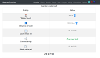
Watmonitor project consists of a central web interface that serves to collect data from sensor IoT nodes and visualize them to the user. Current data on the water level are represented in the dashboard together with the conversion to the volume of the well, historical data on the water level are also available to the user in tabular or graphical visualization with line graphs.
Web interface is responsive, it can adapt to any screen and device resolution. Project's web interface uses a backend written in PHP that can process incoming data from the request using the HTTP POST method. Backend corrects the measured level to the actual one based on the known depth of the well, calculates the volume of water in the well from this parameter and the diameter of the well. Depth and diameter of the well are entered into the system by the user based on the proportions of his well.
Data are sent to the web server by a microcontroller, which performs measurements every 300 seconds - i. 5 minutes, or in the case of transmission via IoT network Sigfox, data is sent every 11 minutes, as it is limited by the network to transmit a maximum of 140 messages per day. Water level measurement is performed using ultrasonic sensors - HC-SR04, or its waterproof variant JSN-SR04T, other sensors with Trigger / Echo signals from US-02X, IOE-SR0X, HC-SR0X, HY-SRF0X, DYP-ME007 series can also be used.
Principle of measuring ultrasonic sensors is to send a Trigger signal with a length of 10 μs (microseconds), which bounces off the water level and returns to the receiver - Echo. Time-of-Flight method is used to recalculate the time between sending and receiving the signal to determine the distance of the water level from the sensor, which is located at the top of the well. Conversion formula takes into account the speed of sound 343 m/s at a temperature of 20 °C.
Important parameter for both ultrasonic sensors is the beam width, in other words the detection characteristic. HC-SR04 sensor has a 15° detection characteristic. The beam is relatively narrow and the sensor is also suitable for narrower wells and tanks, but it is not waterproof and has a high risk of corrosion (oxidation) due to the presence of moisture in the well.
For this reason, it is advisable to place this ultrasonic sensor above the well. Waterproof sensor JSN-SR04T has a detection characteristic of 60°, which considerably limits it and prevents its use in narrow wells, as the beam widens with distance and requires a well with a diameter of several meters (6 meters diameter at a well depth of 4.5 meters). Ultrasonic sensors are fully maintenance-free. The JSN-SR04T sensor has an electronic control board that must not be exposed to moisture and water.
Standard communication shielded cable is 2.5 meters long, it is possible to connect counterparts of the same cable to extend the line. In the case of a square well, the diameter of the inscribed circle is entered into the average, which will form the reference value of the water cylinder for the calculation of the well volume. Error of the total well volume in this case will be similar to ~12.5%. Maximum measurable level height (level) by the sensors is about 400 to 450 cm (known from the datasheet).
Ultrasonic sensors are suitable for applications in:
- Digged wells
- Septics and cesspools
- Streams and lakes
- Plastic rainwater tanks
- Silos (measuring bulk filling)
- Containers (waste monitoring, fill level)
- Boiler rooms (monitoring of wood, pellets, coal, wood chips materials)
- Shafts and cellars (flooding - groundwater monitoring)
Ultrasonic sensors are NOT suitable for applications in:
- Drilled wells (due to detection characteristics - wide beam)
- Pipes and tubes (due to detection characteristics - wide beam)
- To wells with a tributary (rippled surface attenuates ultrasound, measurement is impossible)
- In places with a sudden change in temperature (temperature affects the time of sound propagation, so even the stationary level appears to fluctuate)
- Vacuum tanks (measurement is not possible)
Web interface uses trigonometry to estimate the measurable maximum depth of a well at a known well diameter (another parameter for calculating well volume). Interface allows user to calculate to what maximum depth of the well each of the sensors is suitable based on its characteristics. Project is so easy to use even for laymen who do not know which sensor is more suitable for application in their well. Microcontroller used also plays an important role in the system.
For the project, it is possible to use the Arduino platform (Uno / Mega) in revision R3 with an identical pinout, which can be connected to an Ethernet shield that communicates via the ICSP interface. It is also possible to use Ethernet modules and connect them directly to the hardware SPI pins of the microcontroller. Ethernet modules from Wiznet W5100, W5500, USR-ES1 are supported.
Ethernet module ENC28J60 is from MicroChip is supported too. All Ethernet modules provide HTTP connectivity with the web server. WiFi microcontrollers from Espressif Systems - ESP8266 and ESP32 are also supported. Microcontrollers have several operating modes: StandBy, StandBy + OTA with the possibility of remote firmware upload via LAN network and deep sleep mode for ULP applications - Deep Sleep. In sleep mode for ESP8266 it is necessary to add a physical jumper between GPIO16 (WAKE) and RST - see Wiring Diagram. There is also available experimental implementation for ESP32 in the ESP-IDF framework. It uses FreeRTOS (real-time operating system) and two tasks with Queue mechanism for inter-task data communication
ESP microcontrollers also allow the implementation of HTTPS (encrypted) connectivity with the web server. Both the ESP8266 and ESP32 platforms use the Root CA, which has issued a certificate (Issuer) for the web server domain. The certificate is embedded in the source code of the microcontrollers in.pem format. In order for the certificate not to take up space in the RAM memory of the microcontroller, it is inserted into the flash memory of the microcontroller - PROGMEM. Certificate of the certification authority is valid for 10 to 20 years, so it does not require frequent renewal of the certificate. Data on the current water level and water volume in the well are available in JSON format from the web interface. The project can integrate the Level meter project via MQTT into home automation (Hassio, Domoticz, Loxone) to display the water level in its own dashboard, e.g. Grafana.
At web interface there is also webpage where user can see local records of his water well level. Subpage will print in gauge graphs MAXIMUM and MINIMUM value of water level per 24 hours, 7 days, 30 days..The maximum and minimum water levels can thus be used for continuous monitoring of the well in the individual months of the year, which can serve as an indicator of a drying well or excess water that can be used for other purposes.
Other types of water level sensors that can be integrated (you need to create your own firmware):
- Laser (LiDAR)
- Hydrostatic
- Electrostatic (capacitive / inductive)
- Pressure (differential / with compensating atmospheric pressure sensor)
- Optical
- Mechanical (floater)
- Magnetic (Hall)
- Microwave (radar)
- Note: If the water level is recalculated from the bottom of well on the microcontroller's side, the well depth must be set to 0 cm in the web interface, otherwise results will be not correct.
Project water level monitor can be tested for free with your hardware! If you have compatible ultrasonic sensor and microcontroller, you can visit project webpage, where you can test it: https://martinius96.github.io/hladinomer-studna-scripty/en/
There is also at project webpage pre-compiled (Plug n' play) firmware for ESP8266 and ESP32 boards that let you to try project in seconds, because you don't need to download libraries and compile source code. Pre-compiled firmware is in.bin format and you can upload it to your ESP board via ESPTOOL (included in firmware). Pre-compiled firmware is using WiFiManager library to provide SSID and password to your local network for ESP board to get connectivity. WiFiManager will start ESP in AP mode with SSID --> Hladinomer_AP (no password, open network). You can connect to it with your smartphone or computer.
It will automatically redirect you to Captive Portal (if not, use address 192.168.4.1 in your browser). Then you can add your SSID and password where ESP will connect. After successful connection to your WiFi network, ESP will stop broadcast its SSID and it will start to do measurements and data transmission to web inteface. Set SSID and password is permanently stored in ESP, so in future you will not need to configure it again at next start of microcontroller. In case there will be not saved network available, ESP will again start broadcast its Hladinomer_AP SSID.
Visit also project Github, where you can find source codes for microcontrollers (Arduino, ESP8266, ESP32, Sigfox). There are available source codes for HTTP or HTTPS connection. Tested at latest Arduino Cores (3.0.2 for ESP8266 and 2.0.1 for ESP32): https://github.com/martinius96/hladinomer-studna-scripty/tree/master/examples/Hladinomer
If some user is testing Water level monitor, you can see live datas that its sensor node is sending to interface. For HTTP version visit: http://arduino.clanweb.eu/studna_s_prekladom/?lang=en. For HTTPS version visit: https://hladinomer.eu/?lang=en
2024 update:
During 2024, there were significant changes performed on the web interface. There were added new functionalities, including new charts provider - Justgage plugin with Raphael library for Gauge graphs. Also linecharts (Area charts) were upgraded to ApexCharts with modern look and option to export whole graph or its cutout to many possible formats, such as .jpg, .svg or .csv for further analysis. CSV file possible to use with different analytical software such as MATLAB, or internal presentation under powerpoint / excel analysis.
Minor changes for table visualisations with AJAX that is helpful for dynamic deletion of water level record without needing to relooad the page. For source code available on the page, there was used highlight.js that can visualise code in Arduino IDE like look, very friendly to Arduino community.. There was added optional QR scanner based on Instascan HTML5, using which you can print on your phone's screen information about actual water level without needing to open the web interface or know the exact name of water level sensor node. For the latest info about this project, or if you would like to test it, please use https://your-iot.github.io/Watmonitor/
Also at the moment, there are available program implementations (source codes) for ESP32 and ESP8266 for the latest Arduino Cores. For ESP32 for the latest ESP-IDF core v5.x aswell. Web interface at the moment is pre-generating source code for ESP32 microcontroller that is flagship for this project at the moment. Sadly Sigfox in the meantime almost died in Slovakia, where project of Watmonitor is from. And also Arduino with Ethernet module is too old, and is consuming too much energy.
For the future projects, I think only ESP32 is the reasonable option, it has also PHY Ethernet support via RMII interface I have tested earlier too and its program implementation is available on Github too. There were performed successful tests with ESP32-C6 for WiFi 6 and it is working really well. Hopefully with release of ESP32-C5 to mass production, there will be tests with dual-band wifi too with 5 GHz support!
2025 update:
Watmonitor has 2 public JSON API endpoints, which are used for integration to 3rd party platforms, software for visualisation, but also automation. There can be used various enterprise software, tools, such as: Node-RED, Ignition SCADA, Odoo ERP, AWS IoT Core, ThingsBoard, Grafana, Kibana, Power BI, Tableau, WinCC. Extendable with webhooks for automation (Zapier, IFTTT, n8n, Microsoft Power Automate).
There are some guides available, such as ThingsBoard direct integration of Watmonitor using custom widget creation, or Rule Chain automation. Rule Chain option is good for time series data aswell as it is working Independently based on Generator node of Rule Chain. Custom widget is good for the latest data visualisation.
There was published article on topic of Watmonitor integration within Node-RED that can work as a great middleware software, which can prepare datas from Watmonitor into format of target system for integration requires. This topic is also showing how datas from Watmonitor can be Published into ThingsBoard using MQTT directly from Node-RED flow.
In 2025 there was also created a AR (Augmented Reality) webapp, which allows you based on scanner QR code to visualise dashboard within real world. Its just a simple orbital visualisation, meaning the object is still in set distance from scene camera. Advanced implementation with WebXR can create object on set pleace within room that can even more extend your user experience, but that implementation isnt ready yet, simpler version is better, at least for now.
Try Watmonitor today with your hardware: https://your-iot.github.io/Watmonitor/
Discussion (1 commentaire(s))