
130542 Multipurpose FT232H USB Module
The initial purpose of this project is to connect our ECC bus to a USB interface. But the circuit is more than that. All I/O’s are connected to two connecters to maximize possible applications of this circuit. We used one of the newer USB UART/FIFO ICs from FTDI, the FT232H. This is a Hi-Speed single channel version. So it’s capable of operating at 480 Mbps.
The initial purpose of this project is to connect our ECC bus to a USB interface. But the circuit is more than that. All I/O’s are connected to two connecters to maximize possible applications of this circuit. We used one of the newer USB UART/FIFO ICs from FTDI, the FT232H. This is a Hi-Speed single channel version. So it’s capable of operating at 480 Mbps. If configured as a parallel FIFO interface data transfer speeds up to 40 MB/s are possible. A list from FTDI of typical applications:
Single chip USB to UART (RS232, RS422 or RS485), USB to FIFO, USB to FT1248, USB to JTAG, USB to SPI, USB to I2C, USB to Bit-Bang, USB to Fast Serial Optic Interface, USB to CPU target interface (as memory), USB Instrumentation, USB Industrial Control, USB EPOS Control, USB MP3 Player Interface, USB FLASH Card Reader / Writers, Set Top Box PC - USB interface, USB Digital Camera Interface, USB Bar Code Readers.
For a full description of all features of the FT232H (IC1) it’s best to visit the FTDI web site (www.ftdichip.com) and look for the datasheet. Only circuit specific features are going to be described here (some text is taken from the datasheet). In addition to the two I/O connectors K4 and K5 we also placed connector K3. This connector’s pinout is according to a FTDI USB TTL Serial cable (of course the FT232H should be configured correctly). Jumper JP2 selects the supply voltage connected to K3, +5 V or +3.3 V. Since we also want a 3.3 V power supply available on the I/O connectors a little 3.3 V voltage regulator is added to the circuit. The total maximum output current of the SOT23 version of the XC6206P332MR is a little below 150 mA (5 V input). The internal 3.3 V regulator of IC1 is only used by itself.
The USB interface is straight forward. We used a micro USB connector (K2) to keep the size of the PCB minimal. Diode D4 protects IC1. L3 and L4 reduce the effect of HF noise. We connected an EEPROM to the EEPROM Interface, necessary to configure IC1 to different modes. The EEPROM is programmable in-circuit over USB using a utility program called FT_Prog (available from the FTDI web site). The EEPROM can also be used to customize the USB VID, PID, Serial Number, Product Description Strings and Power Descriptor value of the FT232H for OEM applications. Other parameters controlled by the EEPROM include Remote Wake Up, Soft Pull Down on Power-Off and I/O pin drive strength. If the FT232H is used without an external EEPROM the chip defaults to a USB to asynchronous serial UART (RS232 mode) port device. If no EEPROM is connected (or the EEPROM is blank), the FT232H uses its built-in default VID (0403), PID (6014) Product Description and Power Descriptor Value. In this case, the device will not have a serial number as part of the USB descriptor.
Easiest way to use the circuit is to use the BUS Powered Configuration. This is done by setting jumper JP1 to USB. However the circuit can also be set to Self-powered (JP1 set to ECC). In this case the ACBUS7 pin is used and the option “suspend on ACBUS7 low” should be enabled. For this reason pin 31 is connected via R5 to the 5 V of the USB interface.
To have an indication data is sent and/or received in case the circuit is used as an UART (needed for ECC) two leds (D1 and D2) are connected to ACBUS3 and ACBUS4. FT_Prog has to be used to set the pins in mode RXLED# and TXLED# respectively. We made a few screen dumps from the different settings. We set the drive current for port AC to 8 mA. The leds D3 and D4 need more than 4 mA
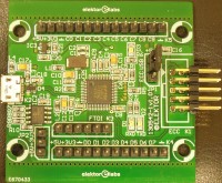
We designed the PCB to fit in a 1455C802 from Hammond Manufacturing. We shortened it to have the PCB fit exactly from one side to the other. The PCB also contains two rows of saw holes as an aid to make the PCB smaller if it’s not used in the before mentioned enclosure. The holes are not meant for breaking! The photos are made of our first prototype. Headers were used (K3/K4/K5) but we decided that sockets protect their connections better against accidental shorts.
Bill of materials
Resistor
R1,R7,R8,R9 = 10 kΩ, 0W1, 1 %, SMD 0603
R2 = 12k0, 0W1, 1 %, SMD 0603
R3,R4 = 220 Ω, 0W1, 5 %, SMD 0603
R5 = 39 kΩ, 0W1, 1 %, SMD 0603
R6 = 1k5, 0W1, 1 %, SMD 0603
R10 = 2k2, 0W1, 1 %, SMD 0603
Capacitor
C1,C2 = 27 pF, 50 V, 5 %, C0G/NP0, SMD 0603
C3,C18 = 10 nF, 50 V, 10 %, X7R, SMD 0603
C4-C9,C11,C13,C14,C16,C19 = 100 nF, 50 V, 10 %, X7R, SMD 0603
C10,C12,C15,C17 = 4µ7, 6V3, 10 %, tantalum, SMD Case R (0805)
C20,C21 = 1 µF, 6V3, 20 %, X5R, SMD 0603
Inductor
L1-L4 = 600 Ω @ 100 MHz, 25 %, 0Ω15, 1A3 (BLM18KG601SN1D, Murata)
Semiconductor
D1,D2,D3 = LED Green, SMD 0805
D4 = PRTR5V0U2X (NXP), SMD SOT-143B
IC1 = FT232HL (FTDI), SMD LQFP-48
IC2 = 93LC56B-I/SN, SMD SOIC-8
IC3 = XC6206P332MR (Torex), SMD SOT-23
Other
K1 = 2x5 header, right angle,
K2 = Micro USB type B, receptacle, bottom, SMD
K3 = 6-way socket SIL, pitch 2.54 mm
K4 = 12-way socket SIL, pitch 2.54 mm
K5 = 14-way socket SIL, pitch 2.54 mm
JP1,JP2 = 3-way pinheader SIL, pitch 2.54 mm
JP1,JP2 = Single shunt jumper 2.54 mm spacing
X1 = Crystal 12 MHz, 18 pF,SMD 5 x 3.2 mm
Misc.
Enclosure 1455C802 Hammond Manufacturing
PCB 130542-1 v1.0
Discussion (1 commentaire(s))