
150455 LED christmas / Carneval ball
Back in 1997 Elektor made a LED Christmas ball with 32 LEDs which were driven by a P87c51 MCU. The project is pretty simple. The MCU drives the LEDs in such a way that it performs neat little effects. Though the project needs to be powered with batteries, so you don't have wires running through the tree.
Back in 1997 Elektor made a LED Christmas ball with 32 LEDs which were driven by a P87c51 MCU. The project is pretty simple. The MCU drives the LEDs in such a way that it performs neat little effects. Though the project needs to be powered with batteries, so you don't have wires running through the tree.
Considering it's almost Christmas (if almost == 5 months), we thought it was time to revive the Christmas ball. But instead of using a P87C51 MCU, I decided to use a ATMEGA328P to drive the 32 LEDs.
The reason I decided for the ATMEGA328P was because it's simple to (re)program the software with an arduino uno. But the downside of the ATMEGA328P against the P87C51 is that the ATMEGA328P doesn't have 32 outputs to drive the LEDs individually.
Because of that little problem, I decided to put the 32 LEDs in a 4x8 LED matrix. That way I only use 12 outputs. I could've used used a 74HC595 shift register to reduce the neccecery outputs, but that would make the PCB design too complicated. Especially because I want to strive towards a circle with a diameter of 70mm (~2.76 inch).
Before I design the PCB, I wanted to test the schematic first. So I grabbed a prototyping PCB and build a prototype (see 150455 1st prototype). I wanted to put the LEDs in a circle formation, but that is kinda difficult with a prototyping PCB. But a square formation is enough to simulate it.
After I wrote a simple program to test the matrix and the brightness of the LEDs. Apperantly the LED brightness seems to be too low (see .150455 1st prototype all LEDs on). After a bit of testing with different LEDs we found a suitable LED (see 150455 1st prototype with new LED).
The reason why the LEDs aren't so bright, is not only because of the reletively high resistor (470 ohms), but also because the LEDs are in a matrix. This project needs to be powered with batteries, or 2 CR2032 in the way I designed it, that's why the resistors have such high values. In the way i designed it, the matrix will power max. 4 LEDs at the same time, and will be updated 8 times to get the full 32 LEDs. The power used by the LEDs will be effectively 1/8 of the power it would've used if it was constantly be powered. I could've gone with a design where max. 8 LEDs will be powered, and where the matrix would update 4 times, making the total power consumption 1/4 of continuously powered, but the max. current through 1 I/O pin of the ATMEGA328P is 40mA which would make the max. current through 1 LED only 5mA(with 8 LEDs at the same time) instead of 10mA (with 4 LEDs at the same time). The 10mA per LED gives me a wider range of current (and thus brightness) to play with.
The only thing that needs to be done now is to design a PCB, and the software. Any ideas for neat effects would be welcome.
Update no.1
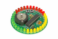
After a bit of designing the PCB has a diameter of 76.2mm, this way the LEDs will fit on the outzide of the circle.
I've replaced the 5-pin header with an ISP connector so users can upload their own pattern and/or code.
The switch, S1, is now connected to pin 4 of the ATMEGA328 so the MCU can be put into, and out of power down modus. The LED row 0 (LED_R0) is now connected to pin 23 of the MCU to make this happen.
I've added another switch so the user can choose between patterns.
A simple code was written to make the matrix work together with a few simple patterns.
Kit available at: http://www.elektor.com/glittering-led-circle-with-arduino-150455-71
Want to build a project?
Bring your design to life with the Elektor PCB Service, powered by Eurocircuits. Upload the project files and order professionally manufactured PCBs or assembled boards through a proven European production platform.
Supporting KiCad, Eagle, Gerber, and ODB++ formats, the service is suitable for everything from prototypes and validation builds to series production and volume manufacturing.
Made in Europe. Fast. Reliable. Professional.
Discussion (2 commentaire(s))