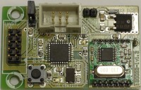
We use our Embedded Communication Connector (ECC), as a gateway module. Our USB-FT232R breakout-board (110553-91) can be connected to this connector (to pins 2/4/6/8), giving it a USB connection. The processor used is a ATmega328P. All data lines to the 433 MHz module are connected to the processor, (including nINT/VDI). We added a push button and a led (D1). Led D2 is a power indicator. A pull-up resistor is connected to nSEL to prevent a programmer sending commands to the RFM12B. Jumper JP1 gives a choice to use a separate power supply for this circuit or use the power available on the ECC. In case an external power supply is used a 5 V regulator (IC2) is present. The input voltage may vary between 6 and 12 V. The regulator is cooled by copper planes on the PCB. Schottky diode D3 is to prevent damage to the circuit in case the external power supply is connected the wrong way round.
Problem is that the original 5 V version of the RFM12 is hard to find. WE used a 3.3 V version instead (RFM12B). The processor won’t run on 16 MHz if its power supply is 3.3V (maybe 12 MHz max.). So we decided to make a little adapter to be placed between the RF module and the PCB. The adapter consists of 8 resistor dividers and a 3.3 V regulator. Originally this adapter was designed as a separate PCB (130023-2) but is integrated on this PCB with version 2.0. Dividers R5/R6 through R19/R20 reduce the 5 V levels to just under 3.3 V. The output signals from the RFM12 to the processor are high enough for the processor to accept without errors. Since the RFM12B only draws a few mA (26 mA max. for the 433 MHz band) this voltage regulator can be very small. We chose one in a SOT-23-3 case. This little regulator can supply 150 mA at 1.7 V between in and output, more than enough for our purpose. The 433 MHZ module is connected to the PCB with the aid of two 2 mm headers and sockets. This makes the removal of the module easy.
An early test setup uses a notebook and a PC. We programmed one prototype as transmitter and another one as receiver, using the software the author supplied. Connected to the ECC of each prototype is a USB-FT232R breakout-board (110553-91). One is connected to the notebook and the other one to the PC. Both are using HTerm as a terminal program. This setup works but there are several issues that need to be addressed. For instance after power-up the RFM12B transmits a carrier wave continuously. Only after transmitting ends the carrier is switched off reducing power consumption by a factor two. If one circuit is programmed as a receiver there is no protection against suppressing noise and disturbances, which is simply being forwarded as data. The present firmware versions do not support bidirectional communication. At this point the firmware needs upgrading.
Here is the BOM.
Bill of materials 130023-1 PCB v2.0
Resistor
R1,R4 = 1 kΩ, 5 %, 125 mW, 0805
R2,R3 = 10 kΩ, 5 %, 125 mW, 0805
R5,R7,R9,R11,R13,R15,R17,R19 = 1k8, 5 %, 100 mW, SMD 0603
R6,R8,R10,R12,R14,R16,R18,R20 = 3k3, 1 %, 100 mW, SMD 0603
Capacitor
C1,C2 = 22 pF, 5 %, 50 V, CG0/NP0, 0805
C3-C7 = 100 nF, 10 %, 50 V, X7R, 0805
C8 = 4.7 µF, 10 %, 6.3 V, X5R, 0805
C9 = 10 µF, -20/+80 %, 25 V, Y5V, 1206
C10,C11 = 1 µF, 20 %, 6V3, SMD 0603, X5R
Semiconductor
D1 = LED Yellow, SMD 0805
D2 = LED Green, SMD 0805
D3 = PMEG2010AEH, 1A, 20 V, SOD-123F
IC1 = ATmega328P-AU, SMD TQFP-32
IC2 = NCP5501DT50G, SMD DPAK-3
IC3 = XC6206P332MR, SMD SOT-23-3
Other
K1 = Header straight, 2x5, 2.54 mm spacing
K2 = Box Header straight, 2x3, 2.54 mm spacing
K3 = 2-way pinheader SIL, 2.54 mm spacing
JP1 = 3-way pinheader SIL, 2.54 mm spacing + jumper 2.54 mm
S1 = Switch tactile 6x6 mm SPST-NO, 12 V 50 mA
X1 = Crystal, 16 MHz, 50 ppm, Cload 18 pF, 5x3.2 mm, SMD ABM3, Abracon ABM3-16.000MHZ-B2-T
MOD1 = RF module, transceiver, FSK, 433 MHz, 3.3 V, Hope Microelectronics co., Ltd RFM12B-433-S1
MOD1 = 2 x header vertical, SIL 7way, 2 mm spacing
MOD1 = 2 x socket vertical, SIL 7way, 2 mm spacing
Misc.
PCB 130023-1 v2.0

Discussion (2 commentaire(s))