
74xx LED clock
Submitted by: Michael (michael.gaus@gmx.de).
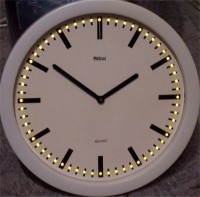
This project uses a standard analog quartz clock and adds 60 LEDs clockwise around it to display the seconds. The whole logic is built without a microcontroller, just using logic devices from the 74xx family.
There are 2 selectable modes via 2 jumpers:
A 1Hz clock is generated by using a crystal oscillator built up with a 4060. The 32768 Hz crystal frequency is divided down to 2 Hz, which is output at Q14. To get a 1 Hz signal, a D-flipflop 7474 is used, connected as toggle flipflop which results in dividing by 2. The 1 Hz signal can be connected to the clock inputs of the shift registers via jumper JP2. In Mode 2 (all 60 LEDs can be controlled externally), the signals /CLEAR, CLK and DATA of the 74164 chain have to be controlled externally via connector J1. For this mode, jumpers JP1 and JP2 both need to be connected to positions 2-3. Supply voltage is generated using a 7805 linear regulator. The input voltage VIN can be in the range from 8V to 15V.
This project uses a standard analog quartz clock and adds 60 LEDs clockwise around it to display the seconds. The whole logic is built without a microcontroller, just using logic devices from the 74xx family.
There are 2 selectable modes via 2 jumpers:
- Every second, each LED is activated one after another. After 1 minute, all LEDs are on. Then every second each LED is deactivated one after another. After 1 minute, all LEDs are off. This is continuosly repeated, so the seconds are visualized by LEDs. This mode uses an integrated 1 Hz timebase and loop-back mode of the shift registers. For this mode, jumpers JP1 and JP2 both need to be connected to positions 1-2 (see schematic).
- All 60 LEDs can be controlled externally, for example by a microcontroller or by a PC. Thereby you have full control of the displayed LED patterns. In this mode, the signals /CLEAR, CLK and DATA of the 74164 chain have to be controlled externally via connector J1. For this mode, jumpers JP1 and JP2 both need to be connected to positions 2-3 (see schematic).
Description of the schematic
In this circuit, 8 serial-in parallel-out shift registers of type 74164 are used to control the 60 LEDs. Each 74164 controls 8 LEDs, except the 8th one which controls the remaining 4 LEDs. The shift registers are cascaded by connecting the last output QH of a 74164 to the inputs A/B of the next 74164. The last output for LED60 can be connected inverted (inverter 7404, IC9A) to the input of the first 74164 via jumper JP1. This is used in mode 1 (clock seconds visualization): after all LEDs have been activated one after another, the inverted pattern is shifted in and all LEDs will be deactivated one after another, which is continuosly repeated. For this mode, jumpers JP1 and JP2 both need to be connected to positions 1-2.A 1Hz clock is generated by using a crystal oscillator built up with a 4060. The 32768 Hz crystal frequency is divided down to 2 Hz, which is output at Q14. To get a 1 Hz signal, a D-flipflop 7474 is used, connected as toggle flipflop which results in dividing by 2. The 1 Hz signal can be connected to the clock inputs of the shift registers via jumper JP2. In Mode 2 (all 60 LEDs can be controlled externally), the signals /CLEAR, CLK and DATA of the 74164 chain have to be controlled externally via connector J1. For this mode, jumpers JP1 and JP2 both need to be connected to positions 2-3. Supply voltage is generated using a 7805 linear regulator. The input voltage VIN can be in the range from 8V to 15V.
Videos
There are two videos available:- http://www.youtube.com/watch?v=LTaV84mTj2w For this video, the clock signal has been put in externally via connector J1 and jumper JP2 in position 2-3 instead of using the integrated 1 Hz clock. This gives a taste of the various possible effects when generating LED patterns externally. By variation of DATA and CLK signals, nice show effects could be created (mode 2).
- http://www.youtube.com/watch?v=UEWgwRypzHk Here you can see the clock working in mode 1, that means as a visualization of the seconds via the 60 LEDs.
Build This Project
Bring this design to life with the Elektor PCB Service, powered by Eurocircuits. Upload the project files and order professionally manufactured PCBs or assembled boards through a proven European production platform.
Supporting KiCad, Eagle, Gerber, and ODB++ formats, the service is suitable for everything from prototypes and validation builds to series production and volume manufacturing.
Made in Europe. Fast. Reliable. Professional.
Discussion (0 commentaire(s))