
A special kind of watch
Display the complete time or date with just 12 colored LEDs. I have set myself the task of creating an electronic binary clock with as few display elements as possible. Each unit of time (hour, minute, second or year, month, day) should be displayed with only four LEDs. With four LEDs, however, it is only possible to display the number range from 0 to 9 in BCD code. One goal was to use only four LEDs to display the maximum number range from 0 to 59 required for hours and minutes.
To do this, the number is first broken down into units of 1 and units of 10.
The units of 1 from 0 to 9 can easily be represented by the usual BCD coding (see Fig.1):
Fig.1 BCD coding
The units of 10 from 0 to 50 that are still required are implemented by setting a color for the four LEDs based on the visible color spectrum from purple to red with increasing wavelength (see Fig. 2):
Fig.2 Spectrum
Figure 3 shows an example of how the number 26 can be represented with four colored LEDs. For better orientation, LEDs that are not set light up discreetly in the background in the color of the 10 value.
Fig.3 Numerical example
The color of the display unit is "green". That makes 20.
The LEDs are set with "0110". That makes 6.
This results in the value 20 + 6 =26
The WS2812B RGB LEDs are ideal for this purpose. The housing contains a controller and the three individual LEDs red, green and blue (see Fig.4).
Fig.4 WS2812B
The WS2812B is controlled via an asynchronous serial protocol (see Fig.5).
Fig.5 protocol
The WS2812 is advantageously available ready-made on small PCBs (see Fig. 6).
Fig.6 WS2812 PCB
With these PCBs, it is very easy to conveniently line up four RGB LEDs each (see Fig.7):
Fig.7 Four RGB LEDs
The simplified block diagram can be seen in FIG. The microcontroller receives the pulse width modulated time information from the DCF receiver module and transfers the time information to the real time clock (RTC). It also generates the protocol that is required for controlling the three RGB LED groups for the time or date. If the Date button is pressed, the date is displayed instead of the time.
Figure 8 block diagram
The specific circuit diagram is shown in FIG.
Fig.9 circuit diagram
Compared to the simplified block diagram, additional functions are implemented in the circuit diagram shown: The clock can be reset with the TA4 button. With the TA3 button, a new synchronization with the time is forced via radio. The phototransistor PT1 enables the brightness of the RGB LEDs to be adjusted depending on the ambient brightness. The DCF receiving module is switched off with the transistor T1 when it is not required. With a BA_1 battery, the RTC continues to be supplied with energy in the event of a power failure.
I decided to realize the project with an ATMEGA32 and to create the software in BASCOM.
The software is not exactly elegantly written because it is made up of individual subprojects.
Listing of the BASCOM_Software see: clock_bas.pdf
The HEX-File of the Software see: clock_hex.pdf
It is certainly better today to implement the task with an ARDUINO, for example.
Fig.10 shows the PCB layout and Fig.11 the assembly plan:
Figure 10 PCB
Fig.11 assembly plan
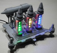
The display and operation of the clock is explained in more detail in FIG
Fig.12 Table clock variant
The design is supposed to be reminiscent of a tube equipped "steam punk device". Therefore, a "tube heater" was imitated with additional red LEDs behind each tube. Most of the housing parts come from the 3D printer.
13 shows a variant as a wall clock. Here the date and time are displayed simultaneously in a total of 6 tubes.
Fig.13 Wall clock variant
14 shows an embodiment in a simple cuboid housing.
Fig.14 Variant simple housing
Admittedly, it seems awkward to read the time.
But I found that after a few days with a little practice you learned to read the time correctly at a glance.
Incidentally, a special feature has to be taken into account when displaying the numbers: the clear year display ends in this millennium at 2059. But there is still a while to go.
When presenting the project, I limited myself to the essentials and wish for imaginative imitators who are inspired by this idea.
The HEX-File of the Software see: clock_hex.pdf
It is certainly better today to implement the task with an ARDUINO, for example.
Fig.10 shows the PCB layout and Fig.11 the assembly plan:
Figure 10 PCB
Fig.11 assembly plan
The display and operation of the clock is explained in more detail in FIG
Fig.12 Table clock variant
The design is supposed to be reminiscent of a tube equipped "steam punk device". Therefore, a "tube heater" was imitated with additional red LEDs behind each tube. Most of the housing parts come from the 3D printer.
13 shows a variant as a wall clock. Here the date and time are displayed simultaneously in a total of 6 tubes.
Fig.13 Wall clock variant
14 shows an embodiment in a simple cuboid housing.
Fig.14 Variant simple housing
Admittedly, it seems awkward to read the time.
But I found that after a few days with a little practice you learned to read the time correctly at a glance.
Incidentally, a special feature has to be taken into account when displaying the numbers: the clear year display ends in this millennium at 2059. But there is still a while to go.
When presenting the project, I limited myself to the essentials and wish for imaginative imitators who are inspired by this idea.
Mises à jour de l'auteur