
Arduino trend recorder
It's a real time trend recorder which works for 30 minutes from right to left. The recorder moves to the left.
Arduino Trend Recorder
If you have the KS0108 64 * 128 graphics LCD display and an Arduino then making a trend recorder is just a Sunday afternoon away. The signal either collected on it's analog pin or digital pin can be plotted beautifully all across the GLCD (Graphical LCD) screen. With little modification more data can be accommodated on the screen.
Trend Recorder how it works :
Trend recorder is something which plots the historical data on the left and the current data on the right. However, while the recorder starts then the data line moves from left to right. As the trend touches the right extreme point then there is no space remains on the right so the entire trend line moves little bit to the left and a new point is accommodated on the right. Once we can master this point, making a trend recorder is just easy.
However, there is one prolific problem with the GLCDs. It has 20 pins to connect. Out of which two pins are 5 volt and ground connections. Of the remaining 18 pins, minimum 14 pins to be connected with the digital pins. Thus leaving very few pins of Arduino free for other important works. To tackle this problem here's one easy way out. Connect the GLCD pins to an Arduino mega or MCP23017 and then operate the GLCD on I2C bus of Arduino. There is one special library available for the same. Thanks to the rich library collections of Arduino. So I prefer the MCP23017 way.
Process:
MCP23017 cost of which is barely Rs:200 from kits' n' spares has 16 digital GPIO pins , 14 of which are connected with the GLCD pins (see schematic) while the MCP23017 is connected to Arduino Uno on I2C bus at analog pin 4 & 5.
Therefore, most of the Arduino pins are set free now. Our data for trend recorder is taken from one digital temperature sensor DS18B20 which is connected on 'one wire' at digital pin-2 of Uno. Simple analog temperature sensor LM35 can also be connected on analog pin. I have one 5 volt stick type temp sensor (DS18B20 – 5 volt) which isused here for sensor.
Any other data like moister content, air pressure etc can also be added very easily. For simplicity we have used only one data here. However, one most interesting trend can be monitored is common domestic tank water level. Summer is all set so monitoring water tank level indicator can be one good use of this trend recorder.
As the program starts it will ask for interval delay value - at which duration the data will be plotted. For entering interval value we have used one pot on analog pin A0. From 0 to 1800 seconds interval can be chosen adjusting the pot. After selecting the value we have used one press-to-on switch on another analog pin A1 which ,when pressed the interval data will be transferred to the program and the trend recorder will be start plotting.
At the beginning the trend line will move from left to right and once the trend line touches the extreme right the entire trend line will be shifted one bit and then redraw from left to right thus creating just one room for the next incoming point to plot. This puts little memory burden on the Arduino but it works. On the top line the the hour ,minute and second lapsed will be displayed along with the temperature value. After plotting nearly two full screen data (242 points) the screen will reset and would start from left again. For highest interval of 30 minute this will plot a trend for 121 hours after which it will reset the data and start over again. However, the time will keep ticking from inception of the first cycle.
Connection Details:
KS0108 PinsConnected to MCP-23017 Pins
1 Ground
2 +5Volt
3 Contrast wiper of 10K Pot
4 26
5 27
6 28
7 1
8 2
9 3
10 4
11 5
12 6
13 7
14 8
15 23
16 24
17 25
18 NC
19 +5Volt
20 Ground
MCP Pins Arduino UNO pins
12 A5
13 A4
Creating Port Address:
MCP-23017 has three address pins – A0, A1, A2, they will be either connected to +5 ve or ground. For each different combination of connections (all three to be connected) , it will create a port address of the chip. The most default address is 0x20 where all A0,A1,A2 are connected to ground. Similarly A0 to +5ve whereas A1 & A2 to ground will create address 0x21 (for more detail see the data book of MCP-23017). After setting the address the same to be entered in the header file – I2C_graphical_LCD_display.h (see where I've marked as “change here for port” ). However, I've set it for the default address as 0x20 for which you need not to do any changes in it.
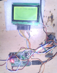
My Prototype:
S. Bera
Vindhyananagr
The Schematic:
If you have the KS0108 64 * 128 graphics LCD display and an Arduino then making a trend recorder is just a Sunday afternoon away. The signal either collected on it's analog pin or digital pin can be plotted beautifully all across the GLCD (Graphical LCD) screen. With little modification more data can be accommodated on the screen.
Trend Recorder how it works :
Trend recorder is something which plots the historical data on the left and the current data on the right. However, while the recorder starts then the data line moves from left to right. As the trend touches the right extreme point then there is no space remains on the right so the entire trend line moves little bit to the left and a new point is accommodated on the right. Once we can master this point, making a trend recorder is just easy.
However, there is one prolific problem with the GLCDs. It has 20 pins to connect. Out of which two pins are 5 volt and ground connections. Of the remaining 18 pins, minimum 14 pins to be connected with the digital pins. Thus leaving very few pins of Arduino free for other important works. To tackle this problem here's one easy way out. Connect the GLCD pins to an Arduino mega or MCP23017 and then operate the GLCD on I2C bus of Arduino. There is one special library available for the same. Thanks to the rich library collections of Arduino. So I prefer the MCP23017 way.
Process:
MCP23017 cost of which is barely Rs:200 from kits' n' spares has 16 digital GPIO pins , 14 of which are connected with the GLCD pins (see schematic) while the MCP23017 is connected to Arduino Uno on I2C bus at analog pin 4 & 5.
Therefore, most of the Arduino pins are set free now. Our data for trend recorder is taken from one digital temperature sensor DS18B20 which is connected on 'one wire' at digital pin-2 of Uno. Simple analog temperature sensor LM35 can also be connected on analog pin. I have one 5 volt stick type temp sensor (DS18B20 – 5 volt) which isused here for sensor.
Any other data like moister content, air pressure etc can also be added very easily. For simplicity we have used only one data here. However, one most interesting trend can be monitored is common domestic tank water level. Summer is all set so monitoring water tank level indicator can be one good use of this trend recorder.
As the program starts it will ask for interval delay value - at which duration the data will be plotted. For entering interval value we have used one pot on analog pin A0. From 0 to 1800 seconds interval can be chosen adjusting the pot. After selecting the value we have used one press-to-on switch on another analog pin A1 which ,when pressed the interval data will be transferred to the program and the trend recorder will be start plotting.
At the beginning the trend line will move from left to right and once the trend line touches the extreme right the entire trend line will be shifted one bit and then redraw from left to right thus creating just one room for the next incoming point to plot. This puts little memory burden on the Arduino but it works. On the top line the the hour ,minute and second lapsed will be displayed along with the temperature value. After plotting nearly two full screen data (242 points) the screen will reset and would start from left again. For highest interval of 30 minute this will plot a trend for 121 hours after which it will reset the data and start over again. However, the time will keep ticking from inception of the first cycle.
Connection Details:
KS0108 PinsConnected to MCP-23017 Pins
1 Ground
2 +5Volt
3 Contrast wiper of 10K Pot
4 26
5 27
6 28
7 1
8 2
9 3
10 4
11 5
12 6
13 7
14 8
15 23
16 24
17 25
18 NC
19 +5Volt
20 Ground
MCP Pins Arduino UNO pins
12 A5
13 A4
Creating Port Address:
MCP-23017 has three address pins – A0, A1, A2, they will be either connected to +5 ve or ground. For each different combination of connections (all three to be connected) , it will create a port address of the chip. The most default address is 0x20 where all A0,A1,A2 are connected to ground. Similarly A0 to +5ve whereas A1 & A2 to ground will create address 0x21 (for more detail see the data book of MCP-23017). After setting the address the same to be entered in the header file – I2C_graphical_LCD_display.h (see where I've marked as “change here for port” ). However, I've set it for the default address as 0x20 for which you need not to do any changes in it.
My Prototype:
S. Bera
Vindhyananagr
The Schematic:
Discussion (0 commentaire(s))