
Current probe for very low frequencies
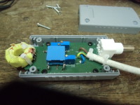
Current probe adapted from a former project to display square waves at low frequencies
Current Probe for Low Frequencies as weel as High Frequencies.
This project builds on the analysis of Mr. Martin Oßmann, Elektor of April and May 2014.
Extension: The pick up coil will also have internal resistance, which limits the lowest frequency. I want to make a current probe which is suitable for very low frequencies.
Case of coil with Ls and Rs, shunted by a parallel resistor of Rp.
See fig 1 Model of current transformer .
For the current transformer we assume one primary winding and N secondary windings, N usually in the range of 10 to 100.For simplicity we assume a coupling of k = 1. Then for the secondary voltage to the scope we find:
Ip jω * Ls
U = --- * ----------------------
N Rs + Rp + jω * Ls
The lowest frequency will be determined by
2 * π * Ls
fg = ------------
Rs + Rp
The transfer ratio for high frequency becomes again:
Rp
Rtr = ----- (without the 50 Ω adaptation network).
N
With the help of electronics we can get a reasonable sensitivity and have a low corner frequency. For example:
fig 2. Using simple electronics
For simplicity we assume an ideal amplifier. Then the inverting input of the amplifier will be on ground level and all the current from the transformer will flow into R1. The current from the transformer will be
Ip jωLs
I = ----- * --------------
N jωLs + Rs
So for the output voltage Vu we can write
: Ip -jωLs
Vu = ----- * -------------- * R1
N jωLs + Rs
Vu -jωLs * R1
----- = Rtr =--------------------
Ip N * (jωLs + Rs)
This has a high pass characteristic. For high frequencies Rtr approaches:
-R1
Rtr = -----
N
The corner frequency is
: Rs
fg = -----------
2π * Ls
For this situation we can have the lowest fg, but it will often prove not to be low enough. If we want to investigate a square waveform with a first harmonic in the range of fg then the response will look like (simulation):
fig 3. Response of squarewave with frequency fg
For displaying a square wave the fg needs to be much lower than the base frequency of the square wave. We can calculate the needed ratio. If we require a droop of x % during the half period p of the square wave then:
x
1- e(-p/2τ) = ----- with τ= Ls / Rs
100
For low x (smaller than 10) this approaches to:
p x
------ = -----
2 * τ 100
With p = 1/ fsquare and τ = 1 / (2 * π * fg) we can write:
2 * π * fg x
---------------- = ------
2 * fsquare 100
Then: fsquare = 100 * π * fg / x
So suppose we allow 2 % droop of a square wave then fsquare needs to be 157 * fg. If we want to investigate pulsed waveforms in the range of 100 Hz, then we must strive for a fg lower than 1 Hz. This can be realised in the above circuit by decreasing Rs. We simply add an negative resistance in series. Then the current from the transformer can get higher at low frequencies. We can realise the negative resistance by applying positive feedback:
fig 4. Adding positive feedback
If a positive current I is flowing from the transformer via Rs to R1, the output Vu will go negative with about I * R1.Then the non-inverting input will also go negative with the amount Vu * R3 / (R2 + R3). The inverting input will go negative with the same amount, as long as the total feedback is negative. The negative resistance seen on the inverting input is:
R1 * R3
------------
R2 + R3
By making this close to Rs the fg of the circuit will be considerably lower. The simulation shows the effect.
Used values:Transformer with Ls = 10 mH, Rs = 1 Ω, N = 100. Opamp: ideal. R1 = 100 Ω, R2 = 100 kΩ, R3 = zero (middle trace) or 950 Ω (top trace).
The lower trace shows the input current, a square wave with DC bias, from zero to 1 A, 20 Hz. The trace in the middle shows the response without negative resistance. The top trace shows the response with an added -0.95 Ω, which lowers the total Rs to 0.05 Ω. Fg is then lowered from 16 Hz to 0.8 Hz.
fig 5. Effect of positive feeback
There is also a negative effect: the relaxation time of the circuit becomes longer. The same simulation with another time axis shows this.
fig 6. Long relaxation time
It takes about 0.6 s to stabilize. This will become more when fg is pushed lower.Roughly:
3 * Ls
t-relax = ------------
(Rs-total)
The above needs to be turned into a practical circuit. Things to solve are:
DC bias;
Prevent that the positive feedback causes oscillations at high frequencies.
I have added fig.7 Proposed principle circuit with the derivation of the transfer function. It turns out that we can have a critical damped system if we adapt the feedback time constant t2 to the timconstant t1 = L / Rtot with Rtot = Rs - R1*R3 / R4.
Temperature co-efficient of copper
The temperature co-efficient of copper is 4.3e-3 / K. So with a temperature variation of 15…..35 °C the resistance of the coil will change ±4.3 % with respect to the value at 25 °C. This makes it dangerous to push fg to the limit. When the temperature goes down too much, the circuit will turn into an oscillator or Schmitt-trigger. We can think about temperature compensation by a NTC resistor in series with R4 (see principle diagram). Then we can lower fg 20 to 50 times with respect to its “bare” value. Without compensation about 5 to 10 times.
Preliminary circuit diagram
The preliminary circuit diagram is given in fig8. IC2 forms the adjustable integrator. By attenuating the output of IC2A, the time constant seen at the output of IC2B is then multiplied with the same amount.
The required positive feedback is made with NTC resistor R2 and series resistor R4 + R6. NTC resistors can be characterized by their B number. The larger the number the larger the temperature dependency. Unfortunately there are many B numbers for the 10kOhm NTCs available. The table at the right gives the values of R4 and R6 when your NTC differs from mine. The B number is normally given by the supplier.
IC2 has a very low bias current and a very low offset. This makes is suitable for this position and work as an integrator. The integrator capacitance is a film capacitor. This type has a low leakage and an high time constant.
Making the coil.
We have to design a toroid coil with a high inductance and a low series resistance. This assures that we have already a low fg to start with. I have made a coil on a TN23/14/7 core with 3E35 material. I made 50 turns with 0,6 mm wire. See fig.9. This gives a coil of about 10 mH with a resies resistance of 0.1 Ω. So L / R ≈ 0.1The wire wich carries the current to be measured will also carry voltage signals, especially when measuring at power supplies. To prevent crosstalk we can shield the coil with copper foil, fig10 and fig11. See fig 12 for a schematic view. The shield can be grounded on the final PCB.
Measuring the prototype
The idea works, we can indeed lower the fg with the positive feedback. However, it is not always that useful. If we use a coil with a low number of turns made with thick wire, the resulting Rs will be low.Because of the low Rs of the coil, the closed loop gain of the circuit without positive feedback is already in the range of one thousand. Adding the positive feedback will indeed lower the fg of the complete circuit but also increases the closed loop gain with a factor of ten to fifty.The result is a lot of noise, which makes the circuit unusable for low amplitudes. To limit the noise I added a resistor of 0.5 or 1 Ω in series with the coil. This limits the closed loop gain to about 100 or 200 and also limits the noise to an acceptable level. Unfortunately the fg will not be that low, but limited to:
1
fg = ------
2πL
With the mentioned coil of 10 mH the noise is just acceptable without using the positive feedback.Fig13 shows the response for a 100 Hz square wave from a pulse generator, loaded with 50 Ω, fig 14 shows the step response for high frequencies. Fig15 shows the stepresponse for low frequencies after alignment of τ2. The positve feedback becomes useful when one wants to measure high currents. Then many turns have to be used, using thin wire. This will lead to a high Rs and also to a low closed loop gain. But also fg will be high. This can be lowered with the positive feedback until the noise becomes irritating.
Building the PCB
The SMD components are mounted on one side of the PCB, the through hole components on the other side. The large integration capacitor can be mounted flat on the PCB. There are three jumper wires, so the PCB could remain double sided.The coil can be fixed at the PCB by two tie wraps. Tie wraps also function as strain relief for the power supply cable. For having a start, do not mount C10 and R23. Also short R24 and R25 temporarely.
Aligning
Start with turning R12 and R14 to minimum resistance. There is now no positive feedback. Consider the noise with your scope in the most sensitive position. If this is acceptable, feed your probe with a square wave current of about 100 Hz. Align the droop with R12 and R14 until it is about 1…2 %. Do not go lower than that: you will end up with a tedious long relaxation time. If the noise is too much in the first step, you will have to bring one or both of the resistors of 1 Ω in the circuit (R24, R25). In that case you cannot use the positive feedback. Next step is the alignment of τ2 with R13. Most handy is a square wave generator with a frequency of 0.1 Hz. If you do not have that, you have to generate step waves your self with a switch, power supply and a suitable resistor. Align R13 until the response resembles fig.15. In some cases, where the alignment is “on the edge”, you might have to adapt R10 to another value.As a last step check the high frequency response with a fast pulse generator. Usually you will find a lot of ringing. With R23 you can damp this ringing. Depending on the coil you might adapt the value. with a lower value, the ringing will be less, but also the risetime will be lower. With C10 you can change the frequency of the rining, if necessary.
Literature
* Negative resistance: Instrumentale Elektronica by G. Klein and J.J. Zaalberg van Zelst, Philips Technische bibliotheek, 1970, chapter 42.
* On the B value of NTC resistors: https://en.wikipedia.org/wiki/Thermistor
Want to build a project?
Bring your design to life with the Elektor PCB Service, powered by Eurocircuits. Upload the project files and order professionally manufactured PCBs or assembled boards through a proven European production platform.
Supporting KiCad, Eagle, Gerber, and ODB++ formats, the service is suitable for everything from prototypes and validation builds to series production and volume manufacturing.
Made in Europe. Fast. Reliable. Professional.
Discussion (1 commentaire(s))