
DIGITAL CIRCUIT GLITCH
Visualization of the simulation of a glitch in a digital circuit
Glitches are terrible things for circuit operation. Among other things, they are hard to see on an oscilloscope, and you may not know they are present. They can give subsequent clocks pulses in flip-flops irregularly, and can be extended or narrowed to extinction - by passing through gates and inverters.
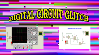
In this simulation I am using a 1Hz clock so that we can see the moment when the glitch occurs more clearly. The glitch occurs when SW1 is set to level 1 (5V), and when it is set back to level 0 (0V or GND) a glitch occurs at the output of the circuit.
The green trace is the clock input from a function generator, the red trace is the output, where the GLITCH appears. The other two lines (purple and blue) refer to the D input and Q output of the flip-flop (74HC74).
Translated from Portuguese with www.DeepL.com/Translator (free version)
Nesta simulação estou usando um clock de 1Hz para podermos enxergar o momento da ocorrência do glitch de forma mais clara. O glitch ocorre quando a chave SW1 é posicionada para nível 1 (5V), quando seu retorno para o nível 0 (0V ou GND) ocorre um glitch na saída do circuito.
O traço verde é o clock de entrada a partir de um gerador de função, o traço vermelho é a saída, local onde aparece o GLITCH. Os outros dois traços (lilás e azul) referem-se a entrada D e saída Q do flip-flop (74HC74).
In this simulation I am using a 1Hz clock so that we can see the moment when the glitch occurs more clearly. The glitch occurs when SW1 is set to level 1 (5V), and when it is set back to level 0 (0V or GND) a glitch occurs at the output of the circuit.
The green trace is the clock input from a function generator, the red trace is the output, where the GLITCH appears. The other two lines (purple and blue) refer to the D input and Q output of the flip-flop (74HC74).
Translated from Portuguese with www.DeepL.com/Translator (free version)
Original post
Glitches são coisas terríveis para operação dos circuitos. Entre outras coisas, eles são difíceis de ver em um osciloscópio, e você pode não saber que eles estão presentes. Eles podem dar pulsos de clocks subsequentes em flip-flops de forma irregular e podem ser alargados ou estreitados até a extinção - através da passagem por portas e inversores.Nesta simulação estou usando um clock de 1Hz para podermos enxergar o momento da ocorrência do glitch de forma mais clara. O glitch ocorre quando a chave SW1 é posicionada para nível 1 (5V), quando seu retorno para o nível 0 (0V ou GND) ocorre um glitch na saída do circuito.
O traço verde é o clock de entrada a partir de um gerador de função, o traço vermelho é a saída, local onde aparece o GLITCH. Os outros dois traços (lilás e azul) referem-se a entrada D e saída Q do flip-flop (74HC74).
Want to build a project?
Bring your design to life with the Elektor PCB Service, powered by Eurocircuits. Upload the project files and order professionally manufactured PCBs or assembled boards through a proven European production platform.
Supporting KiCad, Eagle, Gerber, and ODB++ formats, the service is suitable for everything from prototypes and validation builds to series production and volume manufacturing.
Made in Europe. Fast. Reliable. Professional.
Discussion (1 commentaire(s))