
Easy music - simple pitch follower [130330]
Can’t sing? Don’t know how to play the guitar? With a bit of technology anyone can become a music star!
The idea for this project came when browsing the Elektor Archives. In the book 301 Circuits (from 1983 or so) — the second instalment of the popular Elektor 300 books series — we came across project nr. 14 entitled ‘Easy Music’. According to the project’s description, this little circuit is capable of tracking a melody whistled at its input and then adds a second voice to it. Its output stage consists of a basic power amplifier and a loudspeaker.
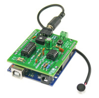
When asked to develop something similar today the first thing we would do, would be to throw an Arduino at it, and this is exactly what we did. In the circuit presented here we have combined the old and the new. The old is the input stage from the Easy Music project, the new is an Arduino Uno or AVR Playground running pitch tracking software. The attached schematic below is the result.
The rest of the job is taken care of by the software executed by the microcontroller on the Arduino Uno board. It continuously monitors the input pin 8 (PB0 on the ATmega328). As soon as an edge is detected — rising or falling — it starts counting microseconds; the next edge of the same type — rising or falling — indicates the end of the period and stops the counter. The measured period is converted to a frequency and compared to a table of musical notes (frequencies). The note nearest in frequency to the measured frequency is selected and a signal with that frequency is output on pin 11 (PB3) to be used as input to another signal processing system (delay, chorus, other).
Since we are using interrupts, it is possible that two parts of the program want to access the variable period at the same time. The ISR might want to update it while another part of the program is reading the value in order to convert it to a musical note. Unfortunately, manipulating multi-byte values are handled by the MCU on a byte per byte basis, meaning that the manipulation can be interrupted between bytes. The ISR has priority over the rest of the program and so it can change the value of period just when it was being read by some other function. It is like watching TV while your roommate is playing with the remote control. When Clark Gable starts off with "Frankly, my dear…” and Clint Eastwood takes over with “… go ahead, make my day", you become confused. The same is true for our program; it can get confused and produce unexpected results.In this atomic block the 4-byte value contained in period is copied to another 4-byte value that is out of reach of the ISR, making it safe to be used whenever required.
Atomic operations are very important in programs where multiple threads or tasks share the same resources (memory, I/O ports, etc.). They are supported by the compiler you use for Arduino sketches as the #include statement shows, it is just that most people don’t know about them.
Adding a MIDI output is another avenue to explore. This is easy enough as the serial port has been left free, and all you have to do is add a table that maps the musical note index to a MIDI key code and generate the appropriate key on and key off messages.
A more difficult exercise is improving the frequency detection when the input signal is more complex than a simple sine-like whistle. At the other hand, the imperfect frequency detection adds an interesting random improvising touch to the system.
The LM3900 is called a Norton amplifier — named after Norton’s theorem — because it amplifies the difference between the currents flowing into its inputs. The opamps that we usually encounter amplify the voltage difference on their inputs. Because the LM3900 has voltage outputs, resistors are necessary to convert the output voltage to input currents. The ratio of the resistor between the positive input and ground (R3 & R6 in figure 1) and the feedback resistor (R4, R7) set the DC output level. Because of its special design it will be clear that it is not possible to replace the LM3900 by “just another opamp”, not in this circuit and probably not in any other circuit based on it.
Application note AN-72 from Texas Instruments entitled ‘The LM3900: A New Current-Differencing Quad of Plus or Minus Input Amplifiers’ explains this device in detail. The LM359 is a high-speed version of (half of) the LM3900.
R2 = 100kΩ
R3,R4,R6 = 5.6MΩ
R5 = 4.7kΩ
R7 = 3.3MΩ
R8 = 27kΩ
R10 = 2kΩ (or 2.2 kΩ)
R11 = 1kΩ
P1 = 47kΩ trimpot
C2 = 10pF, 2.5mm pitch
C3 = 100pF, 2.5mm pitch
C4 = 15pF, 2.5mm pitch
C5 = 100µF, 50V, 2mm pitch
IC2 = LM393
K2 = 10-pin pin header, 0.1” pitch
K3 = 6-pin pin header, 0.1” pitch
K5 = 2-way terminal block, 3.5mm pitch
K6 = 3.5 mm stereo jack socket, PCB mount
DIP-14 IC socket for IC1 (optional)
DIP-8 IC socket for IC2 (optional)
Elektor PCB # 130330-1
When asked to develop something similar today the first thing we would do, would be to throw an Arduino at it, and this is exactly what we did. In the circuit presented here we have combined the old and the new. The old is the input stage from the Easy Music project, the new is an Arduino Uno or AVR Playground running pitch tracking software. The attached schematic below is the result.
A clever combination of hard- and software
The input signal — from a microphone for instance, trimmer P1 controls its sensitivity — is applied to K6. If the input signal is a stereo signal it will be turned into mono first, before it is being amplified by IC1.B and even further by IC1.A. If the input signal does not have too sophisticated a shape, i.e. it has no more than two zero crossings per period — as is the case for a whistle sound —, the signal should now be close to a rectangle wave. IC2.A, a fast comparator, makes the rectangle wave’s edges really steep thus enabling precise frequency measurements.The rest of the job is taken care of by the software executed by the microcontroller on the Arduino Uno board. It continuously monitors the input pin 8 (PB0 on the ATmega328). As soon as an edge is detected — rising or falling — it starts counting microseconds; the next edge of the same type — rising or falling — indicates the end of the period and stops the counter. The measured period is converted to a frequency and compared to a table of musical notes (frequencies). The note nearest in frequency to the measured frequency is selected and a signal with that frequency is output on pin 11 (PB3) to be used as input to another signal processing system (delay, chorus, other).
The sketch in more detail
Pin change (PC) interrupts are used to measure the frequency of the input signal. Since these kinds of interrupts on the ATmega328 trigger on both falling and rising edges, the interrupt service routine (ISR) will consider only one out of every two interrupts. If the input signal has no more than two zero crossings per period, this will be fine. Accepted interrupts are timestamped using the Arduino micros() function and the time difference between two of them will then correspond to the period of the input signal.When Clark Gable turns into Clint Eastwood
The value of the period measured in microseconds does not fit into a single byte. For example, 1 kHz corresponds to a period of 1,000 µs which is larger than 255, the maximum value that fits in a byte. Two bytes can be used for frequencies down to about 15 Hz, so to be on the safe side the period is stored as a 32-bit (4-byte) value (24-bit values are not available).Since we are using interrupts, it is possible that two parts of the program want to access the variable period at the same time. The ISR might want to update it while another part of the program is reading the value in order to convert it to a musical note. Unfortunately, manipulating multi-byte values are handled by the MCU on a byte per byte basis, meaning that the manipulation can be interrupted between bytes. The ISR has priority over the rest of the program and so it can change the value of period just when it was being read by some other function. It is like watching TV while your roommate is playing with the remote control. When Clark Gable starts off with "Frankly, my dear…” and Clint Eastwood takes over with “… go ahead, make my day", you become confused. The same is true for our program; it can get confused and produce unexpected results.
Atomic operations
We have avoided this situation by putting the sensitive part of the program in a so-called atomic block. Atomic here means that the MCU will execute the block without interruption.
#include < util/atomic.h >

uint32_t _period;

ATOMIC_BLOCK(ATOMIC_RESTORESTATE)
{
  _period = period;
}
Atomic operations are very important in programs where multiple threads or tasks share the same resources (memory, I/O ports, etc.). They are supported by the compiler you use for Arduino sketches as the #include statement shows, it is just that most people don’t know about them.
Binary search
Once the period safely copied to a local variable, it can be matched to a musical note. It is very unlikely that there will be a perfect match between the measured and desired frequencies so the program will look for a best fit in a table of possible values. For this the binary search algorithm is a good approach. It starts by comparing the input value to the value in the middle of the table. When it is smaller than the middle value, the search continues in the lower half of the table; if it is higher, the search will continue in the upper half. This procedure is repeated again and again until either a match is found or the table can no longer be cut in half, i.e. there is only one element left. With our 128-note table a search takes on average six iterations (log2(n)-1 where n = 128), making it pretty fast.Octaver
Looking closely at the schematic you will have noticed pushbutton S1 connected to Arduino pin 2 (PD2). This button controls the “octaver” function well known to (bass) guitar players. Pushing it repeatedly will cycle the frequency divider through the values 1, 2, 4 and 8 resulting in an output signal with either the same frequency as the input signal or one, two or three octaves below it.Over to you
Now that we have taken you to the bridge (in James Brown speak) it is up to you to continue. Use the output signal as is or add some processing to it? Change the frequency table, or use the pushbutton for something else?Adding a MIDI output is another avenue to explore. This is easy enough as the serial port has been left free, and all you have to do is add a table that maps the musical note index to a MIDI key code and generate the appropriate key on and key off messages.
A more difficult exercise is improving the frequency detection when the input signal is more complex than a simple sine-like whistle. At the other hand, the imperfect frequency detection adds an interesting random improvising touch to the system.
Retronics: the LM3900 Norton amplifier
Since we copy-pasted the input stage from a 40-year-old circuit, it uses a part that is less common today — yet easily found —, the LM3900. We could copy this circuit verbatim because it is a single-supply design, which was pretty rare for opamp circuits from that period. Its single-supply capability is actually one of the main reasons of being of this IC. We could have replaced the LM3900 by a modern single-supply design, but now we have the opportunity to highlight one of the all-time opamp classics dating back to the early seventies and that is still being produced today.The LM3900 is called a Norton amplifier — named after Norton’s theorem — because it amplifies the difference between the currents flowing into its inputs. The opamps that we usually encounter amplify the voltage difference on their inputs. Because the LM3900 has voltage outputs, resistors are necessary to convert the output voltage to input currents. The ratio of the resistor between the positive input and ground (R3 & R6 in figure 1) and the feedback resistor (R4, R7) set the DC output level. Because of its special design it will be clear that it is not possible to replace the LM3900 by “just another opamp”, not in this circuit and probably not in any other circuit based on it.
Application note AN-72 from Texas Instruments entitled ‘The LM3900: A New Current-Differencing Quad of Plus or Minus Input Amplifiers’ explains this device in detail. The LM359 is a high-speed version of (half of) the LM3900.
Component List
Resistors (0.25W, 5%)
R1,R9,R12,R13 = 10kΩR2 = 100kΩ
R3,R4,R6 = 5.6MΩ
R5 = 4.7kΩ
R7 = 3.3MΩ
R8 = 27kΩ
R10 = 2kΩ (or 2.2 kΩ)
R11 = 1kΩ
P1 = 47kΩ trimpot
Capacitors
C1,C6,C7 = 100nF, 5mm pitchC2 = 10pF, 2.5mm pitch
C3 = 100pF, 2.5mm pitch
C4 = 15pF, 2.5mm pitch
C5 = 100µF, 50V, 2mm pitch
Semiconductor
IC1 = LM3900IC2 = LM393
Miscellaneous
K1,K4 = 8-pin pin header, 0.1” pitchK2 = 10-pin pin header, 0.1” pitch
K3 = 6-pin pin header, 0.1” pitch
K5 = 2-way terminal block, 3.5mm pitch
K6 = 3.5 mm stereo jack socket, PCB mount
DIP-14 IC socket for IC1 (optional)
DIP-8 IC socket for IC2 (optional)
Elektor PCB # 130330-1
Want to build a project?
Bring your design to life with the Elektor PCB Service, powered by Eurocircuits. Upload the project files and order professionally manufactured PCBs or assembled boards through a proven European production platform.
Supporting KiCad, Eagle, Gerber, and ODB++ formats, the service is suitable for everything from prototypes and validation builds to series production and volume manufacturing.
Made in Europe. Fast. Reliable. Professional.
Discussion (0 commentaire(s))