
Build an ESP32 RC Submarine with FPV Camera | ESP-DIVE
Build your own ESP32 FPV Submarine - the ESP-DIVE. A fully functional, Wi-Fi-controlled underwater vehicle with live video feed, adjustable buoyancy, and realistic movement - powered by smart design and open-source code.
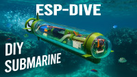
The ESP-DIVE is a DIY submarine you can build to explore the underwater world in first-person view. Watch live video through its front-facing bubble cam, adjust buoyancy to dive or surface like a real sub, and steer it effortlessly from your phone.
I’m Max - and in this tutorial, I’ll give you everything you need: files, code, waterproofing tricks, and step-by-step guidance to build your own fully functional RC submarine and take it exploring wherever you dare to dive.
So buckle up and let’s “DIVE” in!
1. Gathering Parts and Files

To bring the submarine to life, you’ll need things like batteries, a wireless charger, brushed motors with a driver, servo motors, the ESP camera with its SD card, potentiometers, connectors, through-hole and surface-mount components, a PCB, wires, a 5-meter coaxial cable with antenna, rods, straws, screws, inserts, bearings, magnets, and weights. You’ll also need O-rings, tubing, a clear ornament shell, syringes, and an acrylic pipe for the hull.
Here’s the full parts list with links:
- (x1) XIAO ESP32S3 Sense Camera - https://amzn.to/4nGmjcp / https://www.seeedstudio.com/XIAO-ESP32S3-Sense-p-5639.html?utm_source=youtube&utm_medium=MaxImagination&utm_campaign=ESP-DIVE ($13.99 - 23.99)
- (x1) 3.7-5V Boost Converter Module - https://amzn.to/4219Wzg ($0.70)
- (x1) 5V1A Wireless Charger Coil Modules (TX + RX) - https://amzn.to/4pusvpp ($11.86)
- (x1) DRV8833 1.5A Dual Motor Driver Module - https://amzn.to/41YS7kf ($1.40)
- (x1) 050 High-torque Brushed DC Motor - https://amzn.to/3K8Y1cr ($5.88)
- (x3) SG90 Servo Motors - https://amzn.to/42CaY4N ($5.99)
- (x2) N20 104-RPM Geared Motors - https://amzn.to/4ptvJJK ($6.66)
- (x12) 3mm Bright White LEDs - https://amzn.to/42u3K2M ($0.24)
- (x1) 47µF Electrolytic Capacitor (THT) - https://amzn.to/3K6kyGY ($0.03)
- (x1) N/O Reed Switch - https://amzn.to/4nFm7tZ ($0.99)
- (x1) SI2300DS N-MOSFET - https://amzn.to/46gVHaA ($0.14)
- (x1) SI2301DS P-MOSFET - https://amzn.to/3K8cZPR ($0.07)
- (x2) BC847B NPN Transistors - https://amzn.to/4ndPweQ ($0.18)
- Resistors - 0805 SMD (From Kit):https://amzn.to/3X3Mi2l ($0.14)
- (x12) 150Ω
- (x2) 10KΩ
- (x1) 47KΩ
- (x1) 51KΩ
- (x3) 100KΩ
- (x1) 1MΩ
- (x2) 10KΩ Linear Slide Potentiometers (60mm) - https://amzn.to/4nu0pJg ($5.40)
- (x4) 10KΩ Rotary Trim Potentiometers - https://amzn.to/3K8Eau8 ($0.13)
- (x3) JST PH-2.0 2-pin Female & (x1) Male Connector - https://amzn.to/4mie59j ($0.70)
- (x1) Male & Female Pin Header Row Pair - https://amzn.to/4gDumEA ($0.79)
- (x1) DC-005 DC Power Jack - https://amzn.to/4n5yxv5 ($0.27)
- (x1) 5-meter SMA Coaxial Cable - https://amzn.to/4prVsm3 ($7.99)
- (x1) U.FL-1 to SMA Antenna Adapter - https://amzn.to/46wETN9 ($1.56)
- (x2) Servo 3-wire cables with connectors - from two of the disassembled servos
- 20-AWG Electrical Wire (~300mm Red & Black) - https://amzn.to/47OBZpd ($0.67)
- (x2) 500mAh 3.7V 1S LiPo Batteries - https://amzn.to/42DrjGr ($10.99)
- (x1) Dive Controller Board PCB: Order from JLCPCB - https://jlcpcb.com/?from=MaxImagination ($2.00)
- (x1) 4-64GB (32GB) Micro SD Memory Card - https://amzn.to/4n3tCLf ($4.26)
- (x6) M1.6 Screws - https://amzn.to/3Vn0J0s ($0.04)
- (x2) Servo Screws - Included with Servos
- M3 Screws (by length) - https://amzn.to/46snYLE ($0.09)
- (x5) 6mm (Two must be round-headed or grinded round)
- (x3) 16mm
- (x8) M3 Threaded Inserts - https://amzn.to/3Is5Qti ($0.30)
- (x16) Neodymium Rare Earth Magnets (5x3mm) - https://amzn.to/48kSB87 ($1.33)
- (x28 (+-3)) 0.25oz Iron Wheel Weights (7g) - https://amzn.to/4gE35lh ($3.99)
- (x3) Plastic-glass Ball Bearing (3x9x3mm) - https://amzn.to/4nB3JSU ($5.40)
- (x2) 2.2mm Spray Can Straws: Cut in 3 sections (77, 32, & 32mm) - https://amzn.to/46FxJau ($0.16)
- (x1) 2mm Bicycle Steel Spoke - https://amzn.to/4gx6tP1 ($0.75)
- (x2) Rubber O-rings (3.5mm W, 44 OD, 37mm ID) - https://amzn.to/3K1Bi29 ($3.20)
- (x10 (+-5)) Heat-shrink tube - https://amzn.to/4gxSvfF ($0.15)
- (x1) Transparent Plastic Ornament Shell (40mm) - https://amzn.to/46zu7G2 ($0.28)
- (x2) 5mL Syringes - https://amzn.to/48nnkl4 ($1.49)
- (x1) Clear PVC Tube: 300 & 80mm L (3x6mm (ID/OD)) - https://amzn.to/4pz2CVM ($0.66)
- (x1) Clear Acrylic Pipe (44x48x305mm) - https://amzn.to/4nFRvZm ($8.75)
- (x1) Polystyrene Sheet - Find for free in discarded packaging
- 3D Printer Filaments (~$4 USD):
- Army Green PLA - https://amzn.to/3JYIdsJ
- Matte Black PLA - https://amzn.to/3K0coQi
- Glues:
- Superglue - https://amzn.to/4nIhyz7 ($8.99)
- Hot Glue Stick - https://amzn.to/4n8WWA3 ($0.01)
- Epoxy - https://amzn.to/4gqvH1g (Optional)
- Additional:
- (x2) M3 12mm Screws & hex nuts for Pipe cutter clamp - M3 screws kit ($0.04)
Altogether, you’re looking at roughly $125 USD (as of 18/9/25) in parts that go into the sub, not including spare parts, shipping fees, or the price of the 3D design.
To save more, find parts from the list you may already have at your disposal or can acquire locally for cheap.
Project Files - (PCB Files, Schematic, and RTR Code): https://drive.google.com/drive/folders/1DiSvwND1y_ihd31ceJY6NEj7EEpBI6VJ?usp=sharing
3D model/design of ESP-DIVE’s Parts (STLs): https://cults3d.com/en/3d-model/game/esp-dive-an-esp32-rc-submarine-with-fpv-camera-3d-design-stl-files
2. The 3D Design

I spent over a month perfecting the ESP-DIVE’s design so you don’t have to. You can get your hands on all the STLs and g-code to 3D print it here: https://cults3d.com/en/3d-model/game/esp-dive-an-esp32-rc-submarine-with-fpv-camera-3d-design-stl-files
Once downloaded, you can first customize the models or print them as-is using the included g-code files and settings listed on the page.
3. 3D Printing The Submarine's Parts

While I originally printed the sub in PLA, I learned it’s not ideal for long water exposure - PETG or ABS are highly recommended to prevent leaks.
For best results:
- Build volume: 320 × 320 × 385 mm (smaller printers will work too).
- Bed adhesion: enable brim mode to stop tall parts from detaching.
- Supports: turn them on for smoother overhangs; disable for propeller-like parts.
- Print speed: slow down for structural pieces to maximize layer adhesion and strength.
4. Getting The Dive Controller PCB

While wiring up all the components inside the submarine, we’ll use this PCB I designed to keep the control circuit compact and organized.
The Submarine’s ‘Dive Controller’ Board.
Here’s how to order it:
Get a quick quote from your PCB manufacturer by uploading the free Gerber file I’ve linked in the description. Just make sure a few key settings are correct:
- Keep it at 4 layers - super important for this design.
- Choose how many PCBs you want.
- Set the board thickness to 1.6 mm.
- Pick your favorite board color.
- And select “Remove Mark” to keep the board clean from printed order numbers.
Then simply add it to your cart and check out - the whole process takes just a few minutes.
For my batch of 5 PCBs, given the color and complexity, the total was just $6.80 at the time, and JLCPCB had them fabricated in only 3 days (excluding shipping). In the default green, you can get this board for as low as $2.
5. Installing SMD Components

Let’s start assembling the board by applying a bit of solder paste and placing the top-side components: the 51 kΩ and 47 kΩ resistors for voltage monitoring, the 10 kΩ pull-down resistor, and the N-channel MOSFET that drives the headlights.
Once everything’s in place, we’ll heat each pin with a soldering iron to melt the paste - or, if you have one, use a hot plate to reflow everything at once.
For the remaining components, flip the board over and add another layer of solder paste. Then place the latching power switch parts - the P-channel MOSFET, two NPN transistors, and 10kΩ, 100kΩ, and 1MΩ resistors, along with the 150Ω LED current-limiting resistors.
Once positioned, solder them in carefully using tweezers for precision.
And that’s it for the SMD components!
6. Completing Dive Controller Board

Next, let’s install the through-hole components.
We’ll start with the ESP-camera’s foundation by soldering two 7-pin female header rows on the top side.
On the underside, we’ll insert the 6 and 4-pin male headers for the motor driver and the servo headers. With the pins supported by a piece of paper, we can carefully flip the board and solder those bottom-side pins from the top. After that, we’ll push in the JST battery connector and the 47µF capacitor, solder them, and trim any excess pins.
Back on the underside, we can install and solder the DRV8833 dual-channel motor driver - making sure to keep its orientation correct.
With the motor driver installed, it’s time to add the brain of the sub: XIAO ESP32-S3 Sense.
This compact ESP camera board handles Wi-Fi control, live video, onboard recording, and battery management all in one unit.
We’ll start by soldering on its male pin headers using a perf board for alignment. The battery wires connect from the bottom so the XIAO shares battery power with the Dive Controller PCB. The raised header mount positions the board as far forward as possible inside the bubble for a clear view.
Next, trim any header pins flush which would touch the front cap and install the twelve headlight LEDs, keeping them straight through the face.
Finally, clip on the default antenna, reattach the camera board, and the sub’s control system is complete.
7. Programming Dive Controller

To program the board, connect it to your computer and open the Camera Web Server code by s60sc on GitHub: https://github.com/s60sc/ESP32-CAM_MJPEG2SD
Download and unzip the project, remove “-master” from the folder name, and open the .ino file.
In appGlobals.h, comment out unused ESP boards, enable the XIAO ESP32-S3, and set peripherals and MCPWM to true to activate the motors and LEDs.
For the low-battery blinking headlight, replace the function in peripherals.cpp with the custom version included in the project files - it triggers the headlights to blink when voltage drops below the set limit.
If you’re following along to this exact build, you can skip the above code changes and use the ready-to-run code with my modifications.
To upload the code, head under Tools, select XIAO ESP32-S3, enable CDC on boot, PSRAM, and the default partition scheme, choose the correct COM port, and hit Upload.
When done, copy the provided code’s ‘data’ folder onto a 4GB+ microSD card to store app settings and video footage. Insert it into the XIAO, connect a 1S LiPo battery, and short the reed switch pads on the back of the controller board to power everything up.
8. Setting Up Controller App

Connect your device to the ESP camera’s access-point Wi-Fi, then open a browser and enter the default access-point IP: 192.168.4.1
When the control panel loads, tap Start Stream to view the live feed. If it appears upside down, go to Picture Settings and enable V-flip.
When the control panel loads, tap Start Stream to view the live feed. If it appears upside down, go to Picture Settings and enable V-flip.
Next, open Edit Config → Peripherals, enable Remote Control and Servo Use, then scroll to Voltage Monitoring.
Set the low-voltage warning to 3.5V, assign GPIO 6, and enable voltage check.
Under RC Config, assign pins as follows:
- Headlight: GPIO 43
- Forward motor: 1
- Reverse motor: 2
- Steering servo: 3
Under the Servo tab, repurpose the camera controls for the piston ballasts:
- Pan → Front Piston (pin 4)
- Tilt → Rear Piston (pin 5)
Scroll up, tap Save and Reboot, and the board will restart with your new settings.
Reconnect, refresh the page, and you’ll now see live battery voltage - when it drops below 3.5V, the headlights automatically blink as a warning.
Tap the controller icon to access motor sliders and the headlight button.
In Camera Control, adjust stream resolution; higher values lower framerate. For the best balance, use SVGA (800×600) — about 20 FPS with enough clarity.
Finally, check out the Playback & File Transfers tab to view or download recordings, whether saved manually or triggered by motion detection.
9. Assembling Piston Ballasts

Let’s start with the rear ballast.
Melt in two 3 mm threaded inserts to join the rear mount to the front frame later.
Modify a 5 mL syringe by trimming one of the plunger’s side walls so the rack gear sits flat, and cut off one flange tab. Drill a hole in the remaining tab, mount the syringe, trim any excess plastic, and secure it with an M3 bolt - the front frame should snap cleanly in place.
Next, insert the linear slide potentiometer, straighten its four pins, and secure it with a protruding pin or dab of glue. Slide the rack gear onto the slider and glue its backing to the flat plunger section.
Mount an N20 micro metal gear motor snug against the syringe and secure it with M1.6 screws. Add a drop of glue to the shaft and slide on the worm gear to drive the rack. For control, use a 9 g servo board - desolder it from the servo’s motor and potentiometer, trim the edge if needed, and glue it in place.
Install two rotary trimmer potentiometers to set the plunger’s upper and lower limits. Bend and mirror their pins so they link together, then wire them to the linear potentiometer and servo board as follows:
- Left trimmer’s front pin → first (left) of the 4 linear POT’s pins
- Right trimmer’s front pin → top-left pin at end of linear POT
- Remaining trimmer legs → ground and power pads on servo board
- Center servo board pad → second linear POT pin on left
Connect the board’s motor pads to the motor (reversing polarity later if needed), then solder a 3-wire signal/VCC/GND cable from a disassembled servo. Glue down any loose wires to finish.
The second ballast assembles the same way, but the only difference is that it uses three threaded inserts in different positions.
10. Testing and Tuning Peripherals

Connect both ballasts to the control board for a quick test - ensure the charger LED blinks when the wireless charging coils are placed together, the motor spins both ways, the servo moves smoothly, and the pistons extend and retract.
Now tune each ballast:
- Set the slider to 180 (empty) and adjust the lower trimmer so the piston stops just at the end of travel.
- Set to 0 (full) and adjust the upper trimmer likewise.
- Move the piston back and forth, fine-tuning both until it stops cleanly at 0, 90, and 180 without strain.
Repeat for the second ballast - both should act identically: 180 = empty, 0 = full, 90 = neutral.
Adjusting these piston ballasts in sync allows for level diving and surfacing while running them at different positions lets you tilt the submarine slightly up or down for more control when navigating underwater.
11. Assembling ESP-DIVE's Front Half

Disconnect the test wiring and focus on the front frame, where the wireless charging receiver and power board go.
Extend the coil’s wires, glue the charging board into its cavity, and mount the receiving coil in a gentle curve - bending is safe. Add a 5 mm magnet nearby so the transmitter coil snaps into place when charging.
Prepare the 5V boost converter by desoldering both USB ports for a slimmer fit, then solder short leads for the battery input and boosted output. Mount it in the front slot, route the wires outward, and glue it in.
For power control, install a reed switch (a magnetic momentary switch). Gently bend its pins, slot it into the side cavity, test functionality, then glue it in, trim pins, and solder extension wires.
Next, solder a pair of JST connectors for the drive motor - female side on the controller board.
Wire up the charger board and boost converter to the power input pads (two wires each for battery and 5 V output).
Use two 500 mAh 3.7 V LiPo batteries wired in parallel for double capacity while staying 1S-friendly. To make the joint, solder two female and one male JST connector together in parallel and glue between pins to prevent shorts.
Insert both batteries into their slots, connect them via the parallel joint, and plug into the controller. Tidy the wiring and glue the board in place.
Before soldering the reed switch wires, unplug the battery to avoid powering the board accidentally. Reconnect afterward and verify that the magnetic switch toggles power correctly.
For signal routing, feed a UF.L-to-SMA antenna adapter through the PCB hole and connect it to the XIAO’s port, leaving the SMA end free.
Plug in the servo, rear piston ballast, and front piston ballast in that order. Connect a 6 mm PVC hose to the front ballast barrel, route it through the frame loops, and fasten the ballast with 6 mm M3 screws.
Finally, reconnect the charging coil to its board using the extended wires and seal the joints with heat-shrink tubing.
12. Assembling ESP-DIVE's Rear Half

Start by installing a threaded insert for the rear ballast mount, then secure the drive motor with two M1.6 screws. Mount the 9g rudder servo using its included screws. Attach a short PVC hose to the rear piston ballast, slide it into place, and fasten with a single 16 mm bolt.
With both frame halves ready, join them together and secure with an M3 screw on each side. If needed, grind the heads of standard M3 bolts to fit inside the hull. Route the front ballast hose through to the rear so both hoses protrude.
For wiring, extend the male JST connector, plug it into the female side, glue the joint for stability, and solder the wire ends to the drive motor (you can reverse polarity later if needed). Tidy up the wiring for a clean, organized layout.
Next, extend the antenna to the surface using a 5 meter coaxial cable (2.5 mm thick cable, SMA ends). Route the female end through the rear, loosen the motor slightly to make room, and slip on heat-shrink tubing before connecting it to the ESP camera’s adapter. Use pliers for a firm connection, shrink the tubing to seal against condensation, and glue the joint so it doesn’t obstruct the front piston’s movement.
Finally, attach a short 2.4 GHz antenna to the cable’s end - and with that, the wiring for the submarine is complete!
13. Making Magnetic Couplings

Let’s move on to the mechanical assembly, starting with the magnetic couplings.
Press 5×3 mm neodymium magnets into the coupling slots, alternating their polarity - north, south, north, south. This setup ensures that when paired, the couplings want to snap together firmly yet resist rotation, providing a strong and slip-free drive.
For the rudder couplings, use the same alternating polarity pattern but with only three magnets per coupling. This smaller pair converts the motor’s rotary motion into lateral steering movement.
Seal any couplings that will be exposed to water with a generous layer of superglue to prevent corrosion. For those inside the hull, just a few dabs of glue are enough to hold the magnets in place.
By now, you should have a pair of rudder couplings and a pair for the propeller drive.
To prevent the motor shaft from being pulled outward by magnetic forces, insert a plastic ball bearing into its 3D-printed mount. Push the drive coupling into the bearing and secure it with glue. Then, gently heat the motor shaft and press on the coupling assembly - it should spin freely once seated correctly.
14. Assembling The Tail Cone

Grab the rear cap and melt in two threaded inserts. Only if you 3D printed the parts from PLA (which I do not recommend - instead use PETG or ABS), superglue-coat the rear cap entirely to avoid leaks. PLA acts like a sponge under pressure while PETG is said to hold out water more effectively. Then slip on the 44 mm rubber O-ring to seal the back.
Insert a plastic bearing with glass balls to support the propeller shaft and prevent corrosion, even in salt water.
For the shaft, use a 2.2-2.4 mm spray-can straw - it’s lightweight and rust-proof. Secure it to the driven coupling through the bearing, roughen the contact points, and lock everything in place with epoxy. While it cures, slide a bent 1 mm metal spacer under the coupling to keep proper clearance from the wall.
While that sets, assemble the rudder. Use another plastic straw for the steering rod, insert it into one rudder half, and trim it about 20 mm from the fin. Reinsert it with the receiving magnetic coupling, ensuring a snug fit - this also defines the motion limits.
Install the third plastic bearing at the tail cone’s end to support the propeller shaft, and glue on the rudder shaft bypass connector so the rudder can pivot freely without interfering with the drive shaft. Attach the bottom fin using the same tube length.
Now, join the rear cap (with its propeller shaft) to the tail cone - it should fit tightly. Fasten it with two 16 mm bolts and check that the output shaft spins freely. Before adding the propeller, trim the shaft so about 6 mm protrudes.
With the parts still apart, route the antenna cable through both sections and out the rear of the tail cone. Mount the cable to the rear cap exit hole with superglue, then reinforce with hot glue to make it fully watertight. If you don’t trust hot glue to seal the hole, 2-solution epoxy is a trustworthy alternative.
Once sealed and cured, reassemble the rear section and slide on the propeller. Secure it with a heated LED pin through its holes - this locks it in place but still allows easy removal later for maintenance.
Attach the two heatsinks from the ESP camera kit on top of the motor for cooling during long runs.
Finish the rudder mechanism by fusing a short bicycle spoke into the rudder coupling and inserting it into place. Trim the excess, then mount the servo drive gear and driven rudder gear. Slide the rear section over the coupling, fasten it, and use a pen-tube spacer to limit travel. With the rudder straight, glue the driven gear onto the shaft - and just like that, you have smooth, responsive steering.
Finally, install the piston ballast hoses into the rear cap. Trim them to length, add a thin bead of superglue, press them in with pliers, and seal around the edges for leak protection.
15. Adding Ballast Weights

Next, let’s form the fixed ballast that gives the submarine enough weight to dive.
We’ll use ¼-oz (7g) iron wheel weights - trim the edges, peel off the sticky backing, and press them into the weight mounts on the frame. It holds eight in the front and eight in the back, arranged in rows of four.
Now for the adjustable exo-ballast weights.
Separate each ¼-oz weight, completely remove its backing, and slide it into a piece of heat-shrink tubing. This protects the metal from water, prevents rust, and keeps everything looking neat.
Seal both ends with a small dab of superglue for a watertight finish. Make a handful of extra sealed weights - they’ll come in handy for fine-tuning buoyancy later.
The exo-ballast weight holder later attaches to the submarine using the knobs - it locks securely in place once both end caps are sealed.
16. Sealing The Sub

For the front face, take one half of a 40 mm clear ornament shell and trim off the tab so it’s flush.
Glue the shell into the front cap, ensuring there are no gaps, then add a second layer of glue from the inside for extra sealing. If you 3D printed the parts from PLA (which I do not recommend - instead use PETG or ABS), superglue-coat the front cap piece entirely as PLA absorbs water under pressure like a sponge. Slip on the O-ring to complete the seal.
Before final assembly, test for leaks - submerge the cap underwater and check it after testing. Even if you don’t see bubbles, it doesn’t mean there are no leaks. Repeat the test until it’s completely watertight.
To cut the acrylic pipe, 3D-print the custom pipe cutter holder (STL included). Insert two M3 hex nuts and bolts to complete the tool.
Mark the tube at 288 mm, clamp the cutter in place, and saw through carefully for a straight, clean cut. Deburr the edges with a knife or deburring tool - they’re sharp, so handle with care.
Once trimmed, slide the pipe over the submarine until it meets the rear O-ring and sits snugly in place.
17. Making The Antenna Buoy

Now let’s build the floating buoy that keeps the antenna at the surface.
Hot-wire cut a circle from a thick polystyrene sheet, mark its center, and mount it on a swiveling stick to chamfer the bottom edge for smoother gliding on water.
Cut a slot down to the center hole so the antenna cable can snap neatly into place.
Cover any exposed metal with heat-shrink tubing to prevent corrosion, then seat the antenna snugly in its channel.
Cut a slot down to the center hole so the antenna cable can snap neatly into place.
Cover any exposed metal with heat-shrink tubing to prevent corrosion, then seat the antenna snugly in its channel.
The buoy is complete - it’ll simply trail the submarine as it moves across the water.
18. Assembling The Sub's Wireless Charger

Before testing the sub, let’s set up its wireless charger using the custom 3D-printed casing.
Insert a small magnet for easy clip-on docking, then prep the female DC jack by soldering its wires and pushing it into place.
Desolder the coil from the transmitter board, slot the board into its cavity, and connect the DC jack to the input pads.
Resolder the coil using shortened wires, glue it in position - using the acrylic pipe as a guide for perfect alignment - then fill the electronics cavity with hot glue for durability.
Use a toothpick and marker to highlight the debossed text and icons for a clean finish. Then seal it with a thin layer of superglue for protection.
Power it up with a 12V DC adapter and you now have an isolated clip-on charger - no need to open the sub to recharge.
Charging takes about 8 hours, but as a tip, you can speed it up by adding a TP4056 board inside the sub or instead by charging via USB with the front cap removed.
For the fastest option, use a dedicated LiPo charger with a JST connector for a full charge in roughly 1.5 hours.
As a bonus, you may use the printed stand, giving the ESP-DIVE a proper place to park - even with exo-ballast weights installed. Perfect for display or storage between dives.
And with that - the ESP-DIVE is officially complete, weighing in at 608 grams and ready for its first dive!
19. Troubleshooting Tips

If your first test doesn’t go perfectly, don’t worry - these fixes and improvements will get your ESP-DIVE running smoothly and watertight:
- Prime the front ballast: Use a syringe to pump water into the longest hose until the tank fills and starts operating properly.
- Seal every pore: Disassemble the sub and coat all 3D-printed surfaces (inside and out) with superglue, especially around couplings and O-ring cavities, to eliminate micro-leaks (not necessary if printing with PETG).
- Strengthen O-rings: Apply a light layer of dielectric grease for a tighter, more durable seal.
- Condensation fix: Dry the front dome completely and re-seal it. Add multiple silica-gel packs inside the hull to absorb moisture.
- Improve visibility: Replace the curved bubble window with a flat round pane to eliminate image distortion underwater.
Protect electronics: Brush clear nail polish over exposed circuit boards for added waterproofing. - Enhance print integrity:
- Use PETG or PLA+ filament (PETG preferred for water resistance).
- Print with zero retractions and slightly higher nozzle temperatures to prevent micro-leaks between layers.
- Smooth water flow: If suction through the front hose feels weak, widen the bend at the front using a short pen-tube insert to prevent kinking.
- Prevent seabed scraping: Attach small blobs of polystyrene along the antenna cable to keep it buoyant and off rough surfaces.
- Balance buoyancy:
- Shift three internal weights to the front right, two to the opposite side, and add a couple near the rear piston motor to fix tail-heaviness.
- Use four to five external weights for freshwater and six or seven for seawater, adjusting as needed for perfect level balance.
20. ESP-DIVE's Maiden Dive Test

It’s finally time for the ESP-DIVE’s maiden test dive. Let’s power it up and lower it into a pool and watch as the last air bubbles escape from the tail cone.
Connect to its Wi-Fi network and load the control panel in your browser. Your video recordings will be saved to the microSD card in AVI format, organized neatly in folders for easy playback or transfer to your computer.
For controls, the left slider in the video feed window runs the propeller forward and reverse, while the right slider steers the rudder. For the best experience, tilt your device horizontally to go full-screen - this gives you access to both the camera feed and the ballast controls at the same time. Set both piston sliders to 90 for neutral buoyancy, move them to 0 to dive, and up to 180 to surface.
With a quick two taps on the control panel, command the ballast tanks to fill, making it sink gracefully beneath the surface.
As it’s brought back up to the surface, the piston ballasts can be heard as they work to pump out water.
Driving it around really feels like piloting a true unmanned submarine - not just any underwater drone.
The ESP-DIVE’s turn radius is a bit wider than a typical underwater drone, so it really shines in larger pools or open water. Speaking of which - let’s take it somewhere bigger…
21. ESP-DIVE's Ocean Test

This is the ESP-DIVE’s first real ocean dive - exploring the stunning Caribbean marine life up close!
I’m piloting it from my kayak, keeping within the 50-meter range of the antenna buoy.
With the ballast set to neutral buoyancy, it’s incredible to watch it hover steadily at one depth, just like a miniature research sub.
Thanks to the 5-meter signal cable, we can really explore - gliding near the reef and swimming right alongside the fish.
Key Project Info:
- Battery Life - 30 mins per charge
- Control Range - 50 meters
- Max Depth - 5 meters
- Max Speed - 0.5m/s
- Weight - 608 grams
- Dimensions - 400x90x90 mm (LxWxH), 48 mm hull diameter
- Build Cost - ~$125 USD
22. ESP-DIVE's FPV Cam Footage

The OV3660 camera can capture up to QXGA (2048×1536 px) resolution, offering a big jump in image quality - but only at 5 FPS. For smoother FPV control, I prefer SVGA (800×600) at 20 FPS, which trades some sharpness for a much more responsive live feed.
Imagine exploring your own lake, river, or reef - all with something you built yourself!
Conclusion

All the files, code, and parts list are linked at the top of this blog and in the video description to get you started.
Before you dive in, make sure to follow every waterproofing tip you can - even if it means sealing vulnerable parts with superglue. Water is unforgiving, so take the time to make your sub watertight.
Now that you know how to build the ESP-DIVE and what it’s capable of, I highly recommend watching the full video tutorial linked at the bottom of this post for detailed step-by-step guidance and dive tests.
Can’t wait to see your ESP-DIVE exploring underwater!
Build This Project
Bring this design to life with the Elektor PCB Service, powered by Eurocircuits. Upload the project files and order professionally manufactured PCBs or assembled boards through a proven European production platform.
Supporting KiCad, Eagle, Gerber, and ODB++ formats, the service is suitable for everything from prototypes and validation builds to series production and volume manufacturing.
Made in Europe. Fast. Reliable. Professional.
Discussion (4 commentaire(s))