
ESP32 Weather Station (180468)
Here we present a specific application with a weather station built around the ESP32, which makes all data directly available online.
Lates Firmware and beta releases can be found on out GitHub page
Information on new Firmware can be found here
The ESP32 board is a versatile and very affordable development platform that is quite suitable for all sorts of home automation projects. Here we present a specific application with a weather station built around the ESP32, which makes all data directly available online.
The ESP32 Weather Station measures the usual weather parameters: temperature, wind direction and wind speed, humidity, air pressure and precipitation. With a suitable sensor, such as the Nova Fitness SDS-011 (PM2.5, resolution 0.3 µg/m3), it can also measure the concentration of fine particles. A Bosch BME280 sensor is used to measure the temperature, humidity and air pressure. For wind speed, wind direction and precipitation we use a weather station kit that is available in the Elektor Store.
The ESP32 makes the measurements and can upload the resulting data to Thingspeak or senseBox. Thingspeak is an online database operated by Mathworks, where you can upload data and view it nicely plotted in charts. The data can also be processed with Matlab.
SenseBox acts as a sort of open-source synoptic weather map. Users who have a senseBox kit or other senseBox compatible device can upload their measurements, which are then displayed on a world map and visible to everyone.
The circuit can be powered from a 12 V lead-acid battery. If you would like to use a 12 V solar panel to charge the battery, we have a handy built-in feature for you: the ESP32 can close a relay when the battery is low and open it when the battery is again fully charged. The ESP32 uses a voltage divider with resistor values of 470 kΩ and 100 kΩ to measure the battery voltage, so you can adapt the start and stop points for battery charging in the software if necessary. LED3 indicates the battery charging status. We use a simple FET (T1) as a buffer to drive the relay. Diode D3 acts as a snubber to suppress voltage spikes from the relay coil and protect T1 against premature failure. Resistor R10 limits the base current, while R7 limits the current through LED3, as do resistors R8 and R9 for LED2 and LED1, respectively. A DC/DC converter (IC1) reduces the power supply voltage to 5 V. This converter is a good deal more efficient than a standard 7805 voltage regulator, so it is a better choice for a battery-powered circuit. On the ESP32 board, the 5 V supply voltage is converted to 3.3 V by a type 1117 voltage regulator IC, and this voltage is available on the board’s connector for use elsewhere (that’s where the 3V3 in the schematic comes from).
Diode D4 protects the ESP32 against any overvoltage from the battery (via voltage divider R11/R12), while capacitor C4 suppresses noise spikes to foster stable readout of the battery voltage.
Resistors R4 through R6 are pull-up resistors that are necessary for proper operation of the corresponding signal lines.
The wind sensor consists of a wind vane for measuring the wind direction and an anemometer for measuring the wind speed. The internal resistance of the wind vane changes depending on the wind direction.
We combined a 10 kΩ resistor (R2) with this wind direction dependent resistance to form a voltage divider. The resulting voltage changes when the wind vane sensor resistance changes, and it can be measured by the ESP32.
The anemometer has a reed switch that generates two pulses for each rotation. According to the data sheet, the wind speed in m/s is equal to the pulse frequency (in Hz) multiplied by 0.33. For determination of the rotation frequency, the data sheet says that the time interval between two pulses (in seconds) should be multiplied by 2 (since the sensor generates two pules per rotation), and then the rotation frequency can be calculated as the inverse of this time interval. If you multiply that value by 0.66, you get the wind speed in metres per second. The wind speed in km/h can be calculated by multiplying the speed in m/s by 3.6. In other words, 1 rps corresponds to a wind speed of 2.4 km/h.
To obtain access to the web page, you have to connect to the ESP32 network provided by the ESP32. Then you can open the web page at the IP address 192.168.4.1. Note that with smartphones (e.g. Android) you must temporarily disable mobile data, because smartphones often switch automatically to mobile data if they do not detect an valid Internet connection via WiFi. In that case the configuration page will not be available.
The web page consists of a single HTML file, which in turn consists of three sections. The "style type='text/css'" element at the top defines the appearance of the page, the "body" element contains the structure and content of the page, and the "script" element at the bottom defines the functionality of the page. For the web page to work properly, javascript must be enabled in the web browser.
The communication between the web page and the ESP32 is done via an ‘asynchronous XMLHttpRequest’ on the web page. When the page is loaded, an http request is generated and sent to the ESP32. The ESP32 receives this request and sends an answer back to the web page with the requested settings or values. For example, when you press a Submit button on the web page, a similar request is sent that now contains the values you entered.
Information on new Firmware can be found here
The ESP32 board is a versatile and very affordable development platform that is quite suitable for all sorts of home automation projects. Here we present a specific application with a weather station built around the ESP32, which makes all data directly available online.
The ESP32 Weather Station measures the usual weather parameters: temperature, wind direction and wind speed, humidity, air pressure and precipitation. With a suitable sensor, such as the Nova Fitness SDS-011 (PM2.5, resolution 0.3 µg/m3), it can also measure the concentration of fine particles. A Bosch BME280 sensor is used to measure the temperature, humidity and air pressure. For wind speed, wind direction and precipitation we use a weather station kit that is available in the Elektor Store.
Features
- Measures temperature, wind direction and wind speed, humidity, air pressure and precipitation
- Optional sensor for fine particles: Nova Fitness SDS-011
- Additional ports for Grove sensors or other devices
- Supports Thingspeak and senseBox
- Can be configured on the internal web page of the ESP32
- Operates from a solar panel, 12 V battery, and/or 8-28 V DC adapter
The ESP32 makes the measurements and can upload the resulting data to Thingspeak or senseBox. Thingspeak is an online database operated by Mathworks, where you can upload data and view it nicely plotted in charts. The data can also be processed with Matlab.
SenseBox acts as a sort of open-source synoptic weather map. Users who have a senseBox kit or other senseBox compatible device can upload their measurements, which are then displayed on a world map and visible to everyone.
Hardware
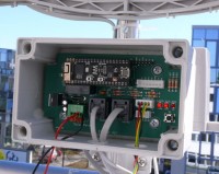
The weather station is built around the ESP32 Pico Kit, which handles all the necessary tasks. To make sensor connection and fitting in a waterproof enclosure (a Fibox PC 100/60 HT) a bit easier, we designed a carrier board. The wind and rain sensors are connected to the carrier board through RJ45 connectors, while the BME280 and SDS011 sensors are connected through JST XH connectors. The BME280 sensor uses the I2C bus, and the SDS011 sensor uses a UART port. We also implemented two additional ports on the board to allow supplementary sensors (or other sensors) or peripheral devices to be read. The first additional port consists of a Grove I2C connector for Grove modules from Seeed studio. The second is an FTDI port that feeds out a UART connection.The circuit can be powered from a 12 V lead-acid battery. If you would like to use a 12 V solar panel to charge the battery, we have a handy built-in feature for you: the ESP32 can close a relay when the battery is low and open it when the battery is again fully charged. The ESP32 uses a voltage divider with resistor values of 470 kΩ and 100 kΩ to measure the battery voltage, so you can adapt the start and stop points for battery charging in the software if necessary. LED3 indicates the battery charging status. We use a simple FET (T1) as a buffer to drive the relay. Diode D3 acts as a snubber to suppress voltage spikes from the relay coil and protect T1 against premature failure. Resistor R10 limits the base current, while R7 limits the current through LED3, as do resistors R8 and R9 for LED2 and LED1, respectively. A DC/DC converter (IC1) reduces the power supply voltage to 5 V. This converter is a good deal more efficient than a standard 7805 voltage regulator, so it is a better choice for a battery-powered circuit. On the ESP32 board, the 5 V supply voltage is converted to 3.3 V by a type 1117 voltage regulator IC, and this voltage is available on the board’s connector for use elsewhere (that’s where the 3V3 in the schematic comes from).
Diode D4 protects the ESP32 against any overvoltage from the battery (via voltage divider R11/R12), while capacitor C4 suppresses noise spikes to foster stable readout of the battery voltage.
Resistors R4 through R6 are pull-up resistors that are necessary for proper operation of the corresponding signal lines.
Rain and wind sensors
The rain sensor consists of a small tray that fills with rainwater. When it is full, it tips and briefly closes a reed switch contact that is monitored by the ESP32. According to the datasheet, each tip of the tray corresponds to 0.33 mm of precipitation.The wind sensor consists of a wind vane for measuring the wind direction and an anemometer for measuring the wind speed. The internal resistance of the wind vane changes depending on the wind direction.
We combined a 10 kΩ resistor (R2) with this wind direction dependent resistance to form a voltage divider. The resulting voltage changes when the wind vane sensor resistance changes, and it can be measured by the ESP32.
The anemometer has a reed switch that generates two pulses for each rotation. According to the data sheet, the wind speed in m/s is equal to the pulse frequency (in Hz) multiplied by 0.33. For determination of the rotation frequency, the data sheet says that the time interval between two pulses (in seconds) should be multiplied by 2 (since the sensor generates two pules per rotation), and then the rotation frequency can be calculated as the inverse of this time interval. If you multiply that value by 0.66, you get the wind speed in metres per second. The wind speed in km/h can be calculated by multiplying the speed in m/s by 3.6. In other words, 1 rps corresponds to a wind speed of 2.4 km/h.
Uploading the software
In order to upload the software to the ESP32, you first have to install the ESP32 Arduino core. Then you have to install the SPIFFS download tool in order to download the web page to the file system of the ESP32 [8]. Once everything is correctly installed, you can select the ESP32 Pico Kit in the boards menu and then download the web page and the sketch.Software
As previously mentioned, the weather station is controlled by the ESP32. You can configure it on a web page hosted directly by the ESP32. When the ESP32 starts up, it tries to connect to the configured network. If that fails, the ESP32 launches the web server that hosts the configuration page. The web server can also be launched manually by pressing the button on the board while switching on power, or by pressing the EN button on the ESP32 module. If the user has not done anything on the configuration page for ten minutes, the ESP32 restarts and connects to the configured network. You can suppress this by keeping the button pressed or bypassing the button. On the configuration page you can view the current measurements as well as the measured battery voltage. You can also configure the network settings and the upload settings. The network settings include the SSID (name) of the network, which can be selected from a list, and the password. The upload settings include the required API keys for Thingspeak and senseBox, as well as the upload interval.To obtain access to the web page, you have to connect to the ESP32 network provided by the ESP32. Then you can open the web page at the IP address 192.168.4.1. Note that with smartphones (e.g. Android) you must temporarily disable mobile data, because smartphones often switch automatically to mobile data if they do not detect an valid Internet connection via WiFi. In that case the configuration page will not be available.
The web page consists of a single HTML file, which in turn consists of three sections. The "style type='text/css'" element at the top defines the appearance of the page, the "body" element contains the structure and content of the page, and the "script" element at the bottom defines the functionality of the page. For the web page to work properly, javascript must be enabled in the web browser.
The communication between the web page and the ESP32 is done via an ‘asynchronous XMLHttpRequest’ on the web page. When the page is loaded, an http request is generated and sent to the ESP32. The ESP32 receives this request and sends an answer back to the web page with the requested settings or values. For example, when you press a Submit button on the web page, a similar request is sent that now contains the values you entered.
Discussion (29 commentaire(s))