
In circuit capacitor tester
Measure capacitors without removing them from a circuit. The method yields proper values even if ssignificant effects by parallel resistance is present. Estimates of parallel resistance as well as ESR can be obtained. Control is based on Arduino.
Measuring capaitance values in the presence of significant leakage due to parallel resistance can be a achieved by the following method:
The presented circuit realises these steps, with microcontroller (ARDUINO UNO) control it may
yield the corresponidng values for C, Rp and (Rs still to be implemented). The excitation voltage U(t) stays below +-100mV, therefore it may be used with electrolytics without bothering about their polarity and further any semiconductor related diode-type connection will not contribute to the current. Thus it may be used for in circuit measurements in many cases.
Due to the synchronous sampling and associated averaging the signal is robusst against external noise.
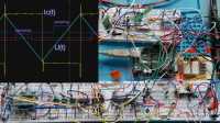
My present realisation is on breadboard only, which is prone to receiving external noise contribution but already yields reliable values. In the attached detailed description examples for curve-forms, sample timings and delay times due to ESR effects a shown and discussed.
Using "zero-offset" high bandwidth op-amps (OPAx388) allows to work with current measuring shunt voltages inte range of 1mV. But the small residual effect of the shunt voltage is further reduced (compensated) by a (positive) feedback of this voltatge to the excitation U(t). In particular this helps to compensate to the shunt contribution to Rs.
Examples on real world measurements are in the detailed description.
Finally let me mention that the same principle can be used for inductivity measurements with only
very few modifications:
In a future sequel I will present this application.
- Apply a voltage than increases or decreases linear in time to the test capacitor. In practice this is achieved by a triangular waveform.
- Measure the current flow through the capacitor.
- Ideally the current Ic is proportional to the capacitance value C times the voltage slope of the triangular "excitation", U(t) ( Ic = dU/dt * C).
- If there is a leakage current through a parallel resistance (Ir = U(t)/R) is will add to the "true" capacitive current.
- However, if the triangular excitation voltage swings around 0 there is an instance where Ir = 0 since U(t)=0. Sampling of the current at that time yields the pure capacitive contribution Ic independent on the prallel resistance.
- Sampling the current at a later (earlier) time further allows to estimate the contribution of the parallel resistor and infer its value.
- In addtion information on a series resistance Rs in the capcitor under test (ESR) may be gainednsince it will cause a characteristic deviation from the ideal response.
- Ideally at change of the voltage slope at the tipping points of a triangular waveform, where the slope dU/dt suddenly chages sign, the current jumps from positive to negative values (or vice versa).
- A series resistance Rs smoothens this sudden transition to an exponetial appraoch with a time constant t = Rs * C. Also measuring this time allows the assessment of Rs.
The presented circuit realises these steps, with microcontroller (ARDUINO UNO) control it may
yield the corresponidng values for C, Rp and (Rs still to be implemented). The excitation voltage U(t) stays below +-100mV, therefore it may be used with electrolytics without bothering about their polarity and further any semiconductor related diode-type connection will not contribute to the current. Thus it may be used for in circuit measurements in many cases.
Due to the synchronous sampling and associated averaging the signal is robusst against external noise.
My present realisation is on breadboard only, which is prone to receiving external noise contribution but already yields reliable values. In the attached detailed description examples for curve-forms, sample timings and delay times due to ESR effects a shown and discussed.
Using "zero-offset" high bandwidth op-amps (OPAx388) allows to work with current measuring shunt voltages inte range of 1mV. But the small residual effect of the shunt voltage is further reduced (compensated) by a (positive) feedback of this voltatge to the excitation U(t). In particular this helps to compensate to the shunt contribution to Rs.
Examples on real world measurements are in the detailed description.
Finally let me mention that the same principle can be used for inductivity measurements with only
very few modifications:
- use the full triangular excitation U(t) prior to attenuation and feed it into an inductor via a (large) resistor Rc, approximately realsing a current source I(t) = U(t)/Rc.
- then the voltage across an ideal inductor is proportional to the slope of current change, yielding a rectangular voltage at the terminals of the inductor Lx (as for the current Ic in the capacitor case).
- any resisstance of the inductor will lead linear varying contribution of the measured voltage then are 0 where I(t)=0, sampling there gets rid of these contributions.Quite analogous to the capcitance case.
In a future sequel I will present this application.
Want to build a project?
Bring your design to life with the Elektor PCB Service, powered by Eurocircuits. Upload the project files and order professionally manufactured PCBs or assembled boards through a proven European production platform.
Supporting KiCad, Eagle, Gerber, and ODB++ formats, the service is suitable for everything from prototypes and validation builds to series production and volume manufacturing.
Made in Europe. Fast. Reliable. Professional.
Discussion (1 commentaire(s))