
IoT based Motion Detection System with ESP32
Are you tired of relying on traditional motion detection systems that require complex wiring and bulky hardware? Then it's time to upgrade to an IoT-based motion detection system with ESP32!
Are you tired of relying on traditional motion detection systems that require complex wiring and bulky hardware? Then it's time to upgrade to an IoT-based motion detection system with ESP32! With this project, you can create a sleek and intelligent motion detection system that's easy to install and control from anywhere in the world.
Using the power of IoT technology, you can receive real-time alerts and even integrate other devices to enhance the system's functionality. Plus, with the ESP32's advanced features, you can customize the system to suit your needs and preferences. In this project, I'll guide you through building your own IoT-based motion detection system with an ESP32, step by step. So, get ready to start an exciting DIY journey and experience the convenience and innovation of IoT technology like never before!
Components
- ESP32 development board
- HC-SR501 PIR sensor module
- LED
- 220-ohm resistor
- Breadboard
- Jumper wires
- Micro USB cable
- Laptop or PC with Arduino IDE installed
ESP32 Development Board
The ESP32 development board is a powerful microcontroller board that is based on the ESP32 chipset. It features built-in Wi-Fi and Bluetooth connectivity, making it an ideal choice for IoT applications. The ESP32 board can be programmed using the Arduino IDE, making it easy to develop and prototype IoT-based projects.
HC-SR501 PIR Sensor Module
A passive infrared (PIR) sensor module called the HC-SR501 can be used to look for people or track their activity. It is frequently employed in IoT projects for applications involving motion detection.
A pyroelectric sensor, a lens, and some electronics are all parts of the PIR sensor module, which processes the sensor's data. The sensor senses a change in the infrared radiation that the object (like a human body) emits when it comes within the sensor's detection range. The pyroelectric sensor in the module notices this shift in radiation, and the electronics in the module process it.
An IoT-based motion detection system can be built using the ESP32 microcontroller and the HC-SR501 PIR sensor module. The ESP32 can activate an action, like turning on a light or transmitting a notification to a smartphone, by reading the output signal from the sensor module with its integrated analog-to-digital converter (ADC).
Additionally, the ESP32 can be configured to interact with other IoT devices, like a home automation system, and initiate various activities in response to motion sensed by the HC-SR501 PIR sensor module.
Breadboard
A breadboard is a prototyping board used for electronics projects. It allows for easy experimentation and testing of electronic circuits without soldering. In this project, the breadboard connects the ESP32 board, PIR sensor, and other components.
Working Principle
The working principle of this project is as follows:
- Any infrared radiation given off by moving objects within the PIR sensor's field of vision is picked up by it. One potentiometer controls the sensitivity, and the other controls the delay time. The sensitivity potentiometer regulates the sensor's range of motion detection, while the delay time slider regulates how long the sensor maintains its HIGH output following motion.
- The ESP32 board receives the PIR sensor's output via one of its GPIO pins. If the output is HIGH, it indicates that motion has been detected. If there is no motion observed, the output will be LOW.
- The ESP32 board uses an LED connected to another GPIO pin to indicate when motion is recognized. Additionally, the SMTP protocol notifies a designated receiver via email. The email's subject is "Motion Detected!" while the content includes the current date and time.
- A web server accessible from any device linked to the same network is also created by the ESP32 chip. The web server displays a straightforward webpage with a message showing whether motion is detected.
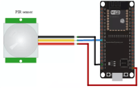
Circuit Diagram
The diagram shows an ESP32 board connected to a PIR sensor and an LED. The PIR sensor has three pins: VCC (5V), GND (ground), and OUT (output). The VCC pin is connected to the 5V pin of ESP32, while the GND pin is connected to the GND pin of ESP32. The OUT pin is connected to GPIO14 of ESP32 through a jumper wire.
The LED has two pins: anode (+) and cathode (-). The anode pin is connected to GPIO2 of ESP32 through a 220-ohm resistor and a jumper wire. The cathode pin is connected to the GND pin of ESP32 through another jumper wire.
The micro USB cable connects the ESP32 board to the laptop or PC for programming and power supply.
Testing the Project
When testing the project, you have to follow these steps:
- Connect the ESP32 board to your laptop or PC using a micro USB cable.
- Open the Arduino IDE, and then from the Tools option, choose the appropriate board and port.
- Change the WiFi credentials and email parameters in the code to your values.
- Compile and send the code to the ESP32 board using the send button.
- Open the serial monitor, and specify 115200 as the baud rate.
- Keep an eye on the LED and serial monitor output while moving your palm in front of the PIR sensor.
- Check your mailbox for an email from ESP32.
You've completed the project's testing if everything performs as anticipated. Congratulations!
Conclusion
An IoT-based motion detection device with ESP32 is a great example of how IoT technology can be used for security and surveillance. The ESP32 board, HC-SR501 PIR sensor module, breadboard, jumper wires, and USB cable simplify designing and testing the system. The ESP32 board controls the device, and the PIR sensor picks up movement within its detection area. Without using solder, it is simple to experiment with and test various electrical circuits using a breadboard and jumper wires.
Discussion (0 commentaire(s))