
Infrared Trail Counter
After a number of delays, fits and starts, and dead ends, I’ve designed an effective, safe (yes, that factors into it as well), and easily deployable trail counter.
After a number of delays, fits and starts, and dead ends, I’ve designed an effective, safe (yes, that factors into it as well), and easily deployable trail counter.
To recapitulate: my friend and neighbor is active in local trail development and maintenance. Demonstrating trail use objectively supports grant applications, donations, and government support. Measuring trail entries and exits is a direct measure of trail utilization, and recording this could potentially be valuable data.
An electronic device capable of this kind of data capture is subject to several design constraints beyond the usual issues of cost, device size, and accuracy. First and foremost is power consumption. Trailheads typically are not near mains, meaning that the device must run on battery power and not require frequent battery recharging or replacement. Second, the device must be people-proof. While a laser beam interrupt system is initially attractive, the scenario of a five-year-old staring at the laser emitter while dad is tying his shoes cannot be discounted. Third, the device must be able to withstand reasonable environmental insults and be easy to deploy. Returning to the laser example, minimal twist, shear, or jarring of the laser emitter may cause the beam to miss the detector unit. Finding an appropriate anchor point and attaching the emitter and detector may be difficult or impossible when alignment specs are so demanding. I’ve addressed this in previous iterations of this project.
Infrared beam interruption arrangements are common. Automatic garage door safety units and entry/exit counters use this technology. Effective and cheap, they are power hungry, with the emitter requiring as much as 300 mA to excite the infrared LED. If the LED is on continuously, battery operation becomes unfeasible.
By repurposing standard, low-power components typically used in TV remote systems, it is possible to reduce emitter current requirements to approximately 2 mA with voltages in the 3-4V range (we’ll get to why a range in a bit…). I have already designed and tested low power circuitry for detection which required only modest alteration.
The design is based on components used in infrared remote controls. To reduce interference, infrared detectors are designed to respond only to infrared energy that is pulsing at a 38 kHz carrier wave. The modulated carrier wave tells your TV to switch to channel 43 and lower the volume.
I used a VS1838B receiver IC. The IC will reject input that is (1) not based on a 38 kHz carrier signal and (2) is not modulated in some manner: a continuous carrier signal is rejected as not carrying data. My design takes advantage of the selectivity and sensitivity of the IR detector. The emitter circuit produces a 10 Hz signal of 1 msec-long pulses of 38 kHz carrier wave. The detector senses the train of incoming pulses. If this train is interrupted, the event is recorded. We’ll get to the specifics in a bit.
The pulse train generator uses a low-current 556IN (two 555 timers in one package). One-half of the unit produces a 38 kHz carrier signal at a 50% duty cycle. The other half of the 556 produces a 10 Hz wave with a 99% duty cycle (remember that 555 circuits can’t have a duty cycle less than 50%). That 10 Hz signal is then inverted (all logic is CMOS), producing a 10 Hz pulse train with each pulse of 1 msec duration.
The two signals are fed into an AND gate, producing a 1 msec long train of 38 kHz pulses 10 times a second. The output is connected to the gate of a logic-level power MOSFET, which in turn controls current to an IR LED. I elected to use a high output, high current LED. Remember, though, that power is applied to the LED (the most power hungry component) for only 0.5% of the duty cycle (power is applied for only 50% of each pulse train). One of the timing resistors in the 38 kHz circuit is a potentiometer so that the circuit can accommodate component imprecision and achieve a (reasonably) precise 38 kHz frequency.
Emitter-side power issues warrant a side discussion. I initially tried to do this “right” with a switching voltage regulator so that the components were working from a 5V regulated power supply. I used cheap generic Chinese buck, generic Chinese buck-boost, and Pololu buck-boost regulators. All components exhibited drastically reduced efficiencies (and correspondingly high power consumption) because the current draw was so low relative to the power requirements of the regulator. Drawing 2mA for the regulator and 2mA for the circuit reduces efficiency to 50%, and halves the battery life. Taking a deep breath, I tried running the emitter straight from a 18560 battery (with my ever-present anti-idiot Schottky diode in the circuit, https://www.elektormagazine.com/news/error-analysis-protect-reverse-polarity) and it worked just fine. CMOS logic and the 556IN chips operate satisfactorily down to 3V, while the 18560 will not drop below 3.5 or 3.75V. The choice of power MOSFET is important. Logic-level MOSFETs can have gate thresholds at 3.3 or 5 volts, so check the specs before ordering. I ended up using monstrous TO-220 packaged MOSFETs, but they had gate thresholds of 3V and milliohm internal resistances. Assuming that the counter would be tended every four weeks, the device could reliably run from a single 18560 battery. Longer maintenance intervals only require a larger battery pack.
Detector, recording circuitry, and programming are variants of previous iterations of this trail counter project. The design is based on a Sparkfun Artemis Nano. This is a low-power device that is easy to program using the Arduino environment. At power-up, the Artemis queries a real time clock with battery backup so that the Artemis’ internal clock can be set. Power is then turned off to the RTC, as this is a high power consumption device. The MCU then monitors the output of the IR detector, measuring the time between detected pulses. If the interval is greater than the threshold, the MCU counts this as an interruption and records the time stamp on an SD card, which is powered only for the write event. I have set my interrupt interval at greater than 200 msec.
Previous testing has shown this circuit to have very favorable power consumption, permitting this half of the system to also be powered from a single 18560 battery, assuming a four-week maintenance cycle. Again, longer maintenance cycles can be achieved with larger battery packs.
Beyond the basic circuit—both the emitter and detector have LEDs that can be turned on and off to assist with troubleshooting and installation. On the emitter side, a visible light LED is in parallel with the IR LED, permitting confirmation that the IR LED is receiving power correctly. The current limiting resistor is removable and replaceable; real world testing showed that higher or lower power output can improve accuracy. If power output is too great, the IR emitter can overwhelm the shadow produced by the walker’s passage. Using the LEDs specified in the BOM, a 51 ohm resistor seems to work well with a 2-3 meter separation between emitter and detector. On the detector side, a visible light LED can be switched into the circuit to confirm that IR pulses from the emitter are being received. This is critical for aiming, installation, and troubleshooting. The device has been tested outside on a bright summer day (but not in direct sunlight) and works correctly.
Previous iterations of the detector circuit raised the concern that powering up the SD card may be a problem for the Artemis’ 3.3V power supply and cause a transient brownout. I’m not sure that this is still true (may have been due to other components and configurations), but in the interests of device reliability the microSD card has its own power supply. I also found that putting a large capacitor in the emitter’s power source prevented voltage dips—the IR LED pulls a lot of current and the capacitor stabilized the performance of the circuit.
The output on the SD card is a .txt file consisting of character strings representing Unix timestamps. Rather than computing and writing out a date/time string, only the Unix timestamp is recorded. Any spreadsheet or other program can easily convert the string into a suitable format. Additional information can be written to the microSD card if needed or desired.
Once the hardware is working and tested, a short program sets the DS3231 clock. The Artemis must be reprogrammed with the detector program after the external RTC time has been set.
Currently, the most recent Arduino environment is not compatible with Artemis. This is a colossal hassle that I hope Sparkfun fixes. Soon!!! I have installed Arduino 1.8.12 on an old external SSD (see instructions for creating a portable Arduino environment on the Arduino website) and use older libraries as well. I’ve included the older libraries with my code.
Readers will note a Configure() function. This function, when invoked, opens a .txt file on the data collection SD card and retrieves and sets operational parameters. I have gotten into the habit of using a Configure function in any project that utilizes an SD card. This allows me to fine tune the function of a device without needing to recompile the program; the entry in the .txt file is changed. This project has only one parameter that can easily be changed by software, the interval that defines an interrupt, and the incremental value of a Configure() function in this instance is limited. However, I still think it is still worthwhile demonstrating in this writeup.
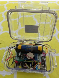
The final consideration is housing and deployment. I used two Pelican 1010 micro cases. The clear plastic transmits IR without difficulty. I have removed the inside liner and used weatherstripping putty to function as a gasket. There are probably other approaches that will work. Theft and vandalism may be a concern, and limiting visibility of or camouflaging the device’s installation may be appropriate.
Acknowledgements and Artificial Intelligence Statement
Except for the 38 kHz carrier signal circuit, all circuits are based on datasheet reference designs or are of original design. The 555 38 kHz carrier signal circuit may be found at robotroom.com/infrared555.html. Thank you! I used Co-Pilot to help calculate the 10 Hz circuit, and I used Grammarly to catch my punctuation and tense errors and, in a few instances, improve awkward wording. Otherwise, AI was not used to write this summary, generate code, or otherwise develop the product.
BOM:
With the exception of the Artemis Nano and the Pololu regulator (S7V8A), I used generic components. The P-channel MOSFET is an NDP6020 and the N-channel MOSFET is a 30N60L. Any 3V logic level, low internal resistance P- or N- MOSFET as appropriate will do. Generic micro SD card readers and DS3231 modules with coin battery backup option are widely available on Amazon, eBay, and other sources. Micro SD cards can be finicky interacting with the inexpensive readers and Arduino environment. Be sure that the microSD card is functioning correctly. The emitter used a 556IN chip, a CD4069 inverter, and a CD4081 AND gate. 18650 batteries are widely available. Realistic mAh capacities for these batteries are between 2500 and 3500. Higher claimed capacities (e.g., 9000 mAh) are not consistent with the battery size and lithium chemistry, and reduce my confidence in the vendor. New individual 18650 batteries should cost USD $5-10; lower prices suggest the item is a refurb. It was a little tough to find the high-output IR LEDs, so here’s the eBay item link: https://www.ebay.com/itm/231172554316 . Digi-Key and Mouser also carry high-output LEDs.
Want to build a project?
Bring your design to life with the Elektor PCB Service, powered by Eurocircuits. Upload the project files and order professionally manufactured PCBs or assembled boards through a proven European production platform.
Supporting KiCad, Eagle, Gerber, and ODB++ formats, the service is suitable for everything from prototypes and validation builds to series production and volume manufacturing.
Made in Europe. Fast. Reliable. Professional.
Discussion (4 commentaire(s))