
Quadrature signal Generator
Quadrature Signals are frequently used. Two clock signals with a 90-degree relation can very easily be created with only two D-FlipFlips. The signals might be used to drive analog circuits like e.g. a quadrature modulator / de-modulator.
Quadrature signal generation
I was browsing/reading ElektorMag: NOVEMBER/DECEMBER 2025
I came across Project 2.0
The item ‘Contactloze E-Veld Metingen (1)’
Elektor 7-8/2025, p. 28 (240279)
There was a discussion about ‘reference’ clocks with a 90 degree shift. A glitch was discussed. I didn’t went back to the article, I just liked to show an improved manner to produce a Quadrature signal generation. The reference clocks mentioned have a frequency of ¼ of the ‘Takt’ clock’s frequency.
Used circuit with glitch
The circuit as discussed in the Project 2.0 item was redraw using ‘Quartus Prime Lite’ from Intel/Altera (FPGA design tool). and simulated. And as correctly discussed in the mentioned Project 2.0 item, indeed the out_8a is corrupted with glitches.
Improved Quadrature signal generation
Improved Quadrature signal generation
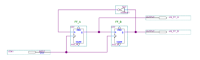
Instead of a feedback of the ‘Q-not’ into the ‘D’ of the same D-Flip Flop, consider a feedback of the inverted-Q of FF_B to reach over the two D-FF’s to feed into the D-input of FF_A. And connect the FF_A/Q to the FF_B/D, and give both the D-FF’s the same ‘Takt’ clock (CLK1).
Here the quadrature-clocks cycles become created by the feedback from the inverted Q of FF_B, and at the same time a 90-degree relation is in the clocks. The outputs oQFF_A and oQFF_B are both very clean glitch-free signals that also have the same Clk -> FF-Q delay. Therefore the Quadrature relation is truly 90.000 degree. Further it is also cheaper as it does not need additional (XOR) circuits.
Improved Quadrature signal generation in practice
Improved Quadrature signal generation in practice
The shown circuit is used internally in a Altera/Intel FPGA. But it can be build using a device out of the famous 7400 series. The 74LS74 contains two D-Flip Flops that can be used :
https://www.build-electronic-circuits.com/7400-series-integrated-circuits/74hc74-74ls74/
Note: It is also possible to use a device 74HC74 or a device out of the 4000 series:
Note: It is also possible to use a device 74HC74 or a device out of the 4000 series:
Using a 74HC74 or a CD4013 is recommended if the quadrature signals are directly used to drive into some analog circuit, that is because the output signals drive over the full range from almost GND up to almost VDD.
A complete pdf-file is included, here al the cirquits and simulation results are shown.
A complete pdf-file is included, here al the cirquits and simulation results are shown.
Build This Project
Bring this design to life with the Elektor PCB Service, powered by Eurocircuits. Upload the project files and order professionally manufactured PCBs or assembled boards through a proven European production platform.
Supporting KiCad, Eagle, Gerber, and ODB++ formats, the service is suitable for everything from prototypes and validation builds to series production and volume manufacturing.
Made in Europe. Fast. Reliable. Professional.
Discussion (0 commentaire(s))