
Railroading, DCC digital accessory system.
RECASTS CONMPLETESYSTEM:Ralroading, digital DCC/RaiCom and CANBus (for command of accessories).Railroading, CANBus control system.
RECASTS CONMPLETESYSTEM:
Ralroading, digital DCC/RaiCom and CANBus (for command of accessories).
Railroading, CANBus control system.
FOR ALL MY FRIENDS’ CONNECTION, I DESIGNED VARIOUS MAPS TO ORDER, WITH ALMOST ALL THE POSSIBILITIES OF USES: SWITCHES, SIGNALS, REVERSE SIGNALING LEDS, LAMPS, RELAYS, ELECTRONIC MODULES, ETC... AND WITH SEVERAL CHOICES OF OPERATING AS WE WILL SEE LATER. THIS SYSTEM IS BASED ON THE MERG CBUS. ALL THESE CARDS ARE MINIS CARDS CMS DOUBLE SIDED WITH ONE SIDE GROUND PLANE, DIMENSIONS: WIDTH OF ± 65MM ± 90MM IN LENGTH, FOR THE MAJORITY OF IT.
As there is lot of maps with a PIC (you know the constructor I hope? No! Is Microchip) and also maps for the railroading in Elektor awhile, I'll enjoy it. Here is the list of these maps, there are eight:
- 1. USB/CANBus interface.
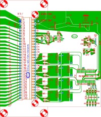
- 2 card drive switches accessories.
- 3 map of standard connections.
- 4 map commands 4 servos, switches or accessories.
- 5 map detections 8 convoys with RailCom©.
- 6 map signaling and or control accessories.
- 7 booster.
- 8 module bridge CANBus.
All of these cards will be compatible to work with most existing systems.
For supplies of different cards, I use the CANBus to power RS-25-5 of 5A to Mean Well and one that you know if you have subscribed to Elektor decades is the power supply 10 A of Elektor n ° 144, June 1990 (French edition) I put three booklets set for 18V / 30A (over 25kg), alternatively there is the MSP-450-15 issuing 30A Mean Well for those who have a very large network and who want a very light weight (1, 2kg for 450W).
The first (photo 1 ) is used as the name suggests interface USB/CANBus to operate all these cards. It send commands signals or get the signals of detections to your management (TrainController© or another for example) of your rail network software to display the names of locomotives (RailCom©) or Open DCC BiDi or other signals.
The second (photo 2 & PCB 1) card is used to control switches and accessories, it can also activate signals to pallets. There will be a table for setting up of different functions, all the outputs can be set separately, for example it can control 4 switches with solenoids, 4 outputs for order 2 switches, relay, leds, etc...; transistors IRF9321PbF of Hexfet© Power MOSFETs of International Rectifier which can cash in pulsed mode -120 A sous -30V, so this side there no problems but which are nevertheless limited to 500mA continuous for my circuits, question dissipation.
It can also turn on leds and lamps with flashing or constant lighting for example lighting on a dock or a street, House, etc... Glue relays to feed a sound module or order more strong power, or a small motor to mill to wind.
In addition there is feedback for the position switches; There will be two types of cards: with feedback and without feedback.
The third map (photo 3) is used to connect different cards; This second card is screwed permanently on the network, so a card command fails, 2 small screws to loosen and hop removed and you replace this defective card by another program with the same functions, therefore you can solder the wires connecting the units on this map.
It receives food, the CANBus and outputs for connecting devices. There's no more to say about this card.
For the fourth (schema 1), it controls four servos to fly four switches, or change signals to pallets, or operate the doors of your Rotunda of the steam depot, or all other things occurring on your network. For this platinum, there's another card connections to connect the servos; you can maneuver that you want, such as usual all the outputs can also be set separately, 2 servos for two switches, one for doors, and the other to rotate the water crane, for example.
It also includes a feedback for the position switches; There also two types of cards: with feedback and without feedback.
The fifth (schema 2) are the responders, detections of 8 convoys with RailCom©, detection this done by current consumption that is compatible with the two and the three rails. It will send by the CANBus trains for the better position signals to the PC which will organize the regularization of the trains rolling.
For signaling is the sixth (schema 3), it can turn on small normal low intensities, consumption led bulbs or low consumption, or operate relays for switching of highest intensity.
All outputs can be set to different European countries: the Belgium, the France, the Germany, the Netherlands, etc. There are also abundantly options for different blocs-system, in the section devoted to this subject as others there will be programs needed to turnialliit.
The seventh (schema 4), as its name suggests is a booster, DCC with Cut-offs for RailCom©, it can provide 4A continuous and 5A peak, it is installed with a (bridge H) L6203 driver PWM controller. 6a / 60V ST Microelectronics Multiwatt, with overload protection circuit. With progressive cooling system.
And to finish the eighth, if you do not have enough with 110 knots, and yes there is a limit to the number of nodes defined by the requirements of the CANBus. Each node requires an integrated circuit transceiver CANBus who posted information on the CANBus. With the available transceivers the number of nodes is set at 110 on a bus "segment". The design of the printed circuit board will follow.
Also I have a big concern, to develop the hardware it's going, but for the software I am nowhere; I'm looking for people who could help me to program the Pics for the various features of the cards. I have programs that can serve as a model and or be implanted such what, according to standards "Layout Command Control (LCC) – OpenLCB" of the M.N.R.A (National Model Railroad Association); If there are people interested, you know how it works, if possible in French, otherwise I will make with the English, thanks.
I'm currently busy drawing boards, I will publish whenever there's a finished.
Mises à jour de l'auteur