
Voltage controlled passive Filter using a common mode choke
This 2nd order filter uses four passive components. Frequency control with a current/voltage. Audio examples are given for synthesizer applications. Manual modulation with a magnet is also possible.
Concept:
This 2nd order audio filter uses only 4 passive components and it's frequency can be tuned over a 1:20 range with a current or with a voltage source + resistor.
The LC-filter has a tunable inductor (1 over 400) that is made with a common mode choke, actually being 2 coils on one ferrite core.
The trick is to use one coil as an inductor in the filter and to use the other coil as control element, changing the ferrite core magnetic susceptibility by gradually saturating it with a dc control current through the control coil. This results in a tunable inductor.
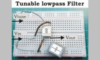
A lowpass filter was realised using this concept, implemented tuning range being 250Hz-5kHz, see circuit diagram. Bandpass was also tested.
Demo sound/video:
Soundexample: "LeftFilterOut-RightFilterIn" is a demonstration of the filter sweeping with a simple static sawtooth as input wave
and a triangular 0.4Hz wave as a control from 0V to 5V. The left channel gives the resulting filter output, the right channel gives the input signal for reference.
A short video shows the filtersweep on the scopescreen.
Soundexample: "Filterchoke-magnet-handcontrol" is a demonstration of the filter being controlled by hand using a magnet on a metal strip that can be bended down (at the end of the soundexample the strip is hit to create vibration).
Details:
In the example circuit it took around 20mA d.c. to fully saturate the core, so a 0-20mA control is needed.
This way you can change the ferrite core susceptibility from it's original value (here approximately 400) down to 1 for full saturation.
Because the cuttoff frequency of an LC filter changes with: 1/ (square root (2PI*L*C)) this means that a 1:400 tuning range for the inductor results in 1:20 tuning range for the filter.
Damping of the filter can be changed from high peaking (synthesizer application?) to damped by changing the resistor value in the control path.
Choke used here was a 2x33mH SMD (bended pins down to fit in breadboard) Epcos number B82792C0336N365.
Other common mode chokes could also be used, see remarks below.
Suggestions:
Another way to control the filter is using a magnet. Put the magnet om a flexible bending strip that you can push down to change the magnet position. For test a small 10mm diameter magnet was used (see pictures). By approaching the core over a distance range of 10 to 2 mm the filter could be tuned full range.
Not needing the second coil now for control gives a possibility to make a double (stereo) filter this way, make an higher order filter or double the inductance. A zero power, no batteries needed, filter can be made this way.
Apart from lowpass, also bandpass and highpassfilters could be made this way.
Remarks/Limitations:
Try to get a common mode choke with a low current handling spec (<0.3A) this means you will need only a small current to saturate it. The choke used here is specified for max 0.1A . To avoid signal distortion, signal levels up to some 100mV should be used. In the lowpass configuration you should drive it with a very low impedance (<5 0hm) to get the full tuning range. The upper frequency (L= almost zero) is dominated by the driver Rout and filter C.
A simple way to get a low impedance driver from a 50 ohm output function generator is to make a resistive attenuator like loading the 50 ohm output with a 2.2 ohm load resistor. Just set the generator to 2V to get 100mV out.
When doing fast (>20Hz) electrical control this control signal is also present in the audio output so this could result in audible effects. To avoid this you could do a compensation trick by using 2 chokes in series and connecting the control coils "anti-serie". Now the control signal crosstalk should be suppressed..
Other filter and synthesizer designs can be found on my personal website: www.rs-elc.nl
This 2nd order audio filter uses only 4 passive components and it's frequency can be tuned over a 1:20 range with a current or with a voltage source + resistor.
The LC-filter has a tunable inductor (1 over 400) that is made with a common mode choke, actually being 2 coils on one ferrite core.
The trick is to use one coil as an inductor in the filter and to use the other coil as control element, changing the ferrite core magnetic susceptibility by gradually saturating it with a dc control current through the control coil. This results in a tunable inductor.
A lowpass filter was realised using this concept, implemented tuning range being 250Hz-5kHz, see circuit diagram. Bandpass was also tested.
Demo sound/video:
Soundexample: "LeftFilterOut-RightFilterIn" is a demonstration of the filter sweeping with a simple static sawtooth as input wave
and a triangular 0.4Hz wave as a control from 0V to 5V. The left channel gives the resulting filter output, the right channel gives the input signal for reference.
A short video shows the filtersweep on the scopescreen.
Soundexample: "Filterchoke-magnet-handcontrol" is a demonstration of the filter being controlled by hand using a magnet on a metal strip that can be bended down (at the end of the soundexample the strip is hit to create vibration).
Details:
In the example circuit it took around 20mA d.c. to fully saturate the core, so a 0-20mA control is needed.
This way you can change the ferrite core susceptibility from it's original value (here approximately 400) down to 1 for full saturation.
Because the cuttoff frequency of an LC filter changes with: 1/ (square root (2PI*L*C)) this means that a 1:400 tuning range for the inductor results in 1:20 tuning range for the filter.
Damping of the filter can be changed from high peaking (synthesizer application?) to damped by changing the resistor value in the control path.
Choke used here was a 2x33mH SMD (bended pins down to fit in breadboard) Epcos number B82792C0336N365.
Other common mode chokes could also be used, see remarks below.
Suggestions:
Another way to control the filter is using a magnet. Put the magnet om a flexible bending strip that you can push down to change the magnet position. For test a small 10mm diameter magnet was used (see pictures). By approaching the core over a distance range of 10 to 2 mm the filter could be tuned full range.
Not needing the second coil now for control gives a possibility to make a double (stereo) filter this way, make an higher order filter or double the inductance. A zero power, no batteries needed, filter can be made this way.
Apart from lowpass, also bandpass and highpassfilters could be made this way.
Remarks/Limitations:
Try to get a common mode choke with a low current handling spec (<0.3A) this means you will need only a small current to saturate it. The choke used here is specified for max 0.1A . To avoid signal distortion, signal levels up to some 100mV should be used. In the lowpass configuration you should drive it with a very low impedance (<5 0hm) to get the full tuning range. The upper frequency (L= almost zero) is dominated by the driver Rout and filter C.
A simple way to get a low impedance driver from a 50 ohm output function generator is to make a resistive attenuator like loading the 50 ohm output with a 2.2 ohm load resistor. Just set the generator to 2V to get 100mV out.
When doing fast (>20Hz) electrical control this control signal is also present in the audio output so this could result in audible effects. To avoid this you could do a compensation trick by using 2 chokes in series and connecting the control coils "anti-serie". Now the control signal crosstalk should be suppressed..
Other filter and synthesizer designs can be found on my personal website: www.rs-elc.nl
Discussion (0 commentaire(s))