
Versatile LED flasher
There are dozens of LED flasher designs on the web. But this design is based on a special complementary transistor combination (which is not a PUT).
To be honest, the following circuit was the result of a trial to design yet another LED fader circuit using an less common combination of 2 complementary transistors.
Nevertheless the circuit is very useful as a LED flasher that is easy to configure to get all kind of flash types.
And, yes, the combination looks like a PUT, but it is not a PUT.
The NPN and PNP transistor in the combination are connected emitter to emitter. This means that one transistor can only conduct when the other transistor also conducts.
It is not possible for one transistor conducts while the other one is not conducting.
And when both are conducting the emitter current of one transistor is equal to the emitter current of the other transistor, so also the collector currents of both transistors must be equal.
At first sight, the transistor combination looks like a PUT (Programmable Unijunction Transistor), but it is not. It does not have the self-latching behaviour of a PUT.
In the following circuits, the transistor combination is used to build a relaxation oscillator.
Again it looks like the PUT relaxation oscillator, but instead of a the self-latching behaviour that is typical for a PUT, the following circuit has a self-cut-off behaviour.
R1, R3 and R4 are given the same value, so it is easier to calculate and understand the voltages in the circuit.
Because R1=R3=R4, the voltage at node 2 will be 1/3th of the power supply voltage. This means that the 2 transistors Q1 and Q2 will conduct when the voltage at node 1 becomes 1,4V (2 forward biased base-emitter junctions) higher than the voltage at node 2.
The voltage at node 3 is 2/3th of the power supply voltage.
After the power supply is switched on, C1 will be charged via R2 and R1. During charging of C1, the voltage over C1 will increase. At the moment that the voltage over C1 (= voltage at node 1) becomes higher than the voltage at node 2 (1/3th of power supply) plus 1,4V (2 forwared biased base-emitter voltages), Q1 and Q2 will start conducting. When Q1 and Q2 conduct, they will pull the voltage at node 3 down to ground.
When the voltage at node 3 goes down to ground, the voltage at node 2 will also drop down. The voltage at node 1 will also drop down fast, because C1 is discharged through the base-emitter junction of Q1 and the collector-emitter of Q2, because both transistors are conducting.
But when the voltage at node 1 has become lower than the voltage at node 2 plus 1.4V (2 forward biased base-emitter junctions), Q1 and Q2 are cut off and stop conducting. At the moment that Q1 and Q2 are cut off, C1 will again charge via R2 and the whole cycle repeats.
So Q1 and Q2 will cut off themselves when they start conducting. That is in fact the opposite of the self-latching behaviour of a PUT, where the transistor keep each other in conduction until the current has dropped far enough so the combination unlatches again.
The circuit of the complementary transistor relaxation oscillator can be adapted to simulate different flash characteristics, such as a long period bright lighthouse flash or a short period fast police flasher.
The constant current source around Q1 in the circuits is added so the current that the circuit draws in "idle" state is not drawn through the LED, but is delivered by the constant current source.
Without the current source, the LED would illuminate due to the small current that is drawn by the circuit when Q1 and Q2 are not conducting and the flasher is in "ïdle" state.
By delivering that small current (1mA) with a constant current source, this current will not be drawn through the LED, so the LED is not illuminated with the circuit in "idle" state.
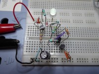
The pictures show 5 configurations of the same circuit, resulting in different flash types :
See the video, in which all configurations are shown.
Nevertheless the circuit is very useful as a LED flasher that is easy to configure to get all kind of flash types.
And, yes, the combination looks like a PUT, but it is not a PUT.
The NPN and PNP transistor in the combination are connected emitter to emitter. This means that one transistor can only conduct when the other transistor also conducts.
It is not possible for one transistor conducts while the other one is not conducting.
And when both are conducting the emitter current of one transistor is equal to the emitter current of the other transistor, so also the collector currents of both transistors must be equal.
At first sight, the transistor combination looks like a PUT (Programmable Unijunction Transistor), but it is not. It does not have the self-latching behaviour of a PUT.
In the following circuits, the transistor combination is used to build a relaxation oscillator.
Again it looks like the PUT relaxation oscillator, but instead of a the self-latching behaviour that is typical for a PUT, the following circuit has a self-cut-off behaviour.
R1, R3 and R4 are given the same value, so it is easier to calculate and understand the voltages in the circuit.
Because R1=R3=R4, the voltage at node 2 will be 1/3th of the power supply voltage. This means that the 2 transistors Q1 and Q2 will conduct when the voltage at node 1 becomes 1,4V (2 forward biased base-emitter junctions) higher than the voltage at node 2.
The voltage at node 3 is 2/3th of the power supply voltage.
After the power supply is switched on, C1 will be charged via R2 and R1. During charging of C1, the voltage over C1 will increase. At the moment that the voltage over C1 (= voltage at node 1) becomes higher than the voltage at node 2 (1/3th of power supply) plus 1,4V (2 forwared biased base-emitter voltages), Q1 and Q2 will start conducting. When Q1 and Q2 conduct, they will pull the voltage at node 3 down to ground.
When the voltage at node 3 goes down to ground, the voltage at node 2 will also drop down. The voltage at node 1 will also drop down fast, because C1 is discharged through the base-emitter junction of Q1 and the collector-emitter of Q2, because both transistors are conducting.
But when the voltage at node 1 has become lower than the voltage at node 2 plus 1.4V (2 forward biased base-emitter junctions), Q1 and Q2 are cut off and stop conducting. At the moment that Q1 and Q2 are cut off, C1 will again charge via R2 and the whole cycle repeats.
So Q1 and Q2 will cut off themselves when they start conducting. That is in fact the opposite of the self-latching behaviour of a PUT, where the transistor keep each other in conduction until the current has dropped far enough so the combination unlatches again.
The circuit of the complementary transistor relaxation oscillator can be adapted to simulate different flash characteristics, such as a long period bright lighthouse flash or a short period fast police flasher.
The constant current source around Q1 in the circuits is added so the current that the circuit draws in "idle" state is not drawn through the LED, but is delivered by the constant current source.
Without the current source, the LED would illuminate due to the small current that is drawn by the circuit when Q1 and Q2 are not conducting and the flasher is in "ïdle" state.
By delivering that small current (1mA) with a constant current source, this current will not be drawn through the LED, so the LED is not illuminated with the circuit in "idle" state.
The pictures show 5 configurations of the same circuit, resulting in different flash types :
- Configuration 1 : Light house flash : bright distinct flash.
- Configuration 2 : Light house flash : a little slower than configuation 1 and with less distinct flash.
- Configuration 3 : Warning light fading in and out.
- Configuration 4 : A little faster than confiiguration 3.
- Configuration 5 : Police flash
See the video, in which all configurations are shown.
Want to build a project?
Bring your design to life with the Elektor PCB Service, powered by Eurocircuits. Upload the project files and order professionally manufactured PCBs or assembled boards through a proven European production platform.
Supporting KiCad, Eagle, Gerber, and ODB++ formats, the service is suitable for everything from prototypes and validation builds to series production and volume manufacturing.
Made in Europe. Fast. Reliable. Professional.
Discussion (0 commentaire(s))