
User Interface for Unilab2 Power Supply
A user interface with LCD and rotary encoders for the Unilab2 power supply.
This project is an add-on for the Unilab2 power supply, published in and at Elektor Labs.
The Unilab2 has a potentiometer to set the output voltage and the maximum current. A carbon film potentiometer tends to wear out prematurely and they are a bit "old school". Also, for reasons of cost, the Unilab2 does not have a display. Setting the current limit is a bit like flying blind, as there is no feedback. The actual value of the current is available as a proportional voltage (on K3) but with quite some tolerance and the voltage must be corrected to obtain the real valiue of the output current.
The Unilab2 has a potentiometer to set the output voltage and the maximum current. A carbon film potentiometer tends to wear out prematurely and they are a bit "old school". Also, for reasons of cost, the Unilab2 does not have a display. Setting the current limit is a bit like flying blind, as there is no feedback. The actual value of the current is available as a proportional voltage (on K3) but with quite some tolerance and the voltage must be corrected to obtain the real valiue of the output current.
My approachnter A 4 x 20 LCD shows nominal voltage, actual power, and the current limit. One rotary encoder is used to set the output voltage and another to set the maximum current in 0.1 V / A steps. Three preset pushbuttons with LED indicator have been added as well. With these buttons one can select one of three fixed output voltages: 3.3 V, 5.0 V, and 12 V.
The actual value of the current is measured with an ACS712 [not suitable for new designs, use AC723 instead] current sensor and captured at the PC1 analog input. The setpoint for the current limitation can be chosen in this mode.
The two LEDs available at the Unilab2 board can be moved to the display board as well.
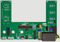
Prototype The project was created in Target V19 and the prototypes are finished. Of course, the board dimensions (160 x 110 mm, W x H) are tailored for my enclosure. A 100 x 60 mm cut-out in the top half provides space for the display. The the copper side of the board is mounted to the front panel with the display plugged "in reverse" on a header on the component side. The rotary encoder is on the right together with the three jacks Plus, Minus, and Ground. The preset voltage pushbuttons are nicely alligned.
When in Preset-Voltage Mode, pressing the built-in pushbutton of the rotary encoder will switch back to Variable-Voltage Mode.
The firmware is written in Bascom. The program and all its functions have been tested extensively on a Breadboard and works fine. I've measured the setpoint voltage at the wipers of the MCP42xxx with two multimeters and they showed exactly the desired values. The Unilab2 expects 0...5 V at the wipers of P3 and P4.
Conclusion If a higher adjustment resolution is desired, a digital potentiometer IC with 512 steps can be used. The MCPxxx has 256 steps.
U_I Display_Unilab2 construction of the prototype variant 2
I have now carried out the test of the prototype variant 1 with the Unilab 2 after exchange R11 = 91K 1% and R12 = 11.3K 1%. This resulted in a very good match of the voltage actual value on the multimeter as well as on the display in idle and under load (5W). I noticed that the Unilab2 at 30V setpoint under load about 500mV higher, but also there very good match. This resistance combination is available from the relevant distributors. An attempt would be worth ordering the two resistors with 0.1%.These resistors should also be used in the final version. Of course, the option with R11 = 100K and R1 = 25K remains open.
There is still a change in the two final versions. I have changed the layout around IC8 (5V fixed voltage IC) so the through-contacts are no longer there under the lying IC. Nevertheless, the mica disc should not be dispensed with.
Conclusion: Those who have the prototype variant V1 under construction can live well with the change of R11 and R12 also with variant. By the way, the three large boreholes serve the banana bushings as a guide to earth U+ and mass.
By the way, AZ Delivery also has the port expander without a display. This would free the way to use a different display and different color.
The two Gerber files with the layout changes are attached. .With version V2 it is also possible to control other power supplies on the setpoint side. Prerequisite setpoint voltage is 0 to 5V.
Yours sincerely
Dieter Aschmann
Power supply front end control version 3
The time has come. The power supply front end control for the Unilab 2 based on MCP49xx has been completed as a prototype. In the current part of the project I used the MCP4912. This DAC has a resolution of 10 bits corresponding to the resolution of the ADC of the ATMega328P. The signal processing of the actual current value is now carried out completely as a hardware solution using MCP602. As a current sensor I used an ACS723 as a +/- 5A variant. It is a BOB with ACS723 from Sparkfun. This variant of the ACS723 provides a voltage of 2.5V at its signal at 0A. An opamp of the MCP602 is connected as a differential amplifier. According to the data sheet, the output of the ACS723 delivers 400mV per ampere. Since a current measurement range from 0 to 5A is programmed in the Bascom project, the signal is multiplied by 2.5 with the 2nd OPV of the MCP602. A reference voltage of 5V is available for the MCP4912 as well as a value set by a precision trimmer for the differential amplifier. The trimmer must be set so that it is attached to the ADC input of the ATMega328P 0V. In the Bascom program it must be noted that the 16 bit wide register of the MCP2912 with bit 0 starting with 12 bits contains data for the output value. But I use the 10 bit variant, so the bits are multiplied by 2 digits to the left here by 4. Then the data word is wrong in memory and the swap statement is used. Subsequently, the data transfer takes place with the sub-routine.
Everything works perfectly. For the setpoints, the fixed values as well as the variable values can be set very precisely. According to the data sheet of the MCP4912, 4.96V should be set at 10 bits. The result measured with my multimeter 4.9x. The x fluctuates around the 5. This cannot be done any better. If you set 3.3V then the setpoint voltage also corresponds to the selection. 15V are very accurate 2.4x V where x oscillates around 5 again. The same result is also achieved by the setpoint of the current limit 3A resulting in 4.9x V also here oscillates x around the 5. 1.5A is linearly beautiful in the middle. I am very satisfied with the measurements, if you want to have the setpoints even closer, you should choose the MCP4922 and make the changes in the well-commented program.
To the actual value display current. ACS723 +/- 5A type I used a wire resistor 10W measured cold resistance 4.7Ohm and connected via an external laboratory power supply 5V +5V to resistance its other end at the +input of the ACS723 (BOB Sparkfun) – the BOB to -5V of the laboratory power supply. After switching on, a current of 1A could be read. The current decreased to 0.92 A with the heating of the resistance. Same procedure with additional multimeters inserted. Both results multimeter and test object were very close to each other. Calculator result is 1.064A. I can be very satisfied with this result. The warming of the resistance actually starts immediately.
The actual value voltage measured and displayed with multimeter accuracy has a very good agreement at 15V and 30V. The voltages are also here from the laboratory power supply.
If you measure R11 and R12 for good agreement, then my measured values result. If the user wants to spend more money then 0.1% tolerance would be an option.
What do current laboratory power supplies have, what does my project not have? Laboratory power supplies have an on/off button my project does not have that and the UNILAB 2 does not have that either.
The MCU no longer has a port pin free, the MCP4912 has a shutdown pin and this is set to +5V = VDD. You can't intervene. After starting frontend, the current setpoint is 0.0A. Therefore, there is no danger for the hardware at first.
I see one possibility in the shutdown pin of the switching regulator IC of the Unilab2. Drag this pin to GND with a latching button and the function would be 100% fulfilled.
It is possible to link my project to other self-made power supplies. Prerequisite is the setpoint voltages must be 0... 5V.
Yours sincerely
Dieter Aschmann
Want to build a project?
Bring your design to life with the Elektor PCB Service, powered by Eurocircuits. Upload the project files and order professionally manufactured PCBs or assembled boards through a proven European production platform.
Supporting KiCad, Eagle, Gerber, and ODB++ formats, the service is suitable for everything from prototypes and validation builds to series production and volume manufacturing.
Made in Europe. Fast. Reliable. Professional.
Mises à jour de l'auteur