
4x4 RGB led game: LUMINEER
A school project I am a student at group T (Leuven) and I study industrial science. I completed my second year now. Together with a team of students, I worked on the course EE4 “Building a lightshow”.
A school project
I am a student at group T (Leuven) and I study industrial science. I completed my second year now. Together with a team of students, I worked on the course EE4 “Building a lightshow”. We had to design a game, which means we had to make something with a goal, with interaction and with a competition factor.
Lumineer
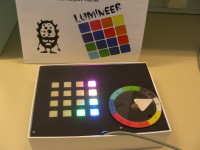
And so we came up with the idea of working with a 4x4 keyboard with RGB-led’s underneath. And a spinning arrow which can both point to colours (all possible colours that can be made by the RGB-led’s without PWM) or numbers. As we worked in a team of 5 people, every teammember was allowed to invent and program his own game, using the keyboard and the arrow.
And now we have 5 games:
- Memory game
- Simon says
- Find the lonely colour
- Reaction test
- Find the lucky colour
The brain
Every student had to use a PCB designed by our school with a PIC 18F2550. On this PCB is also a USB connector to program the microprocessor, some switches to put him in program mode and reset him, some led’s and a big connector to connect the I/O’s from the microprocessor to our self made PCB.
The PIC18F2550 has 18 I/O’s but 2 of them are already connected to the led’s on his PCB, so better not to use these we were told. With 16 I/O’s available we used them as follow:
- 3 I/O’s to control the RGB led’s
- 8 I/O’s to check the switches
- 2 I/O’s to control the stepper motor (1 for a light sensor, and 1 for the steppermotor itself)
To write the program we used MPlab.
The keyboard
The keyboard we used is from Sparkfun (https://www.sparkfun.com/products/7835). To use this we designed our own PCB with Eagle 6 and the library package from Sparkfun.
To save on I/O’s from the microprocessor we used 2 x CD4094 and 2 x UDN2981 to control the RGB led’s underneath the keys.
The steppermotor
To save on I/O’s from the microprocessor we used a L297 and a L298.
First we wanted to put this circuit also on our own PCB, but to save area (and money) our coach gave us a separate PCB with this circuit.
To control the starting position we used a IR reflective optical sensor (CNY70). The bottom of the arrow is covered with aluminium foil so when the arrow comes over this sensor, it detects the arrow.
The box
The box we used is from an Ipad. The size of this box was ideal for our project. We made our own logo and covered the apple logo, than covered everything with a plastic film.
In Fablab (http://www.fablab-leuven.be) we used a laser cutter to make a cover out of plexi with holes for the keys and the motor.
Conclusion: the ingredients
For this project we used:
- the PIC evaluation board from school with a PIC18F2550 microprocessor
- our own PCB
- a PCB with the circuit for the stepper motor
- steppermotor PM55L-048-HHD0 (recycled from an old printer)
- CNY70
- L297 and L298
- silicon keypad
- 16 RGB led’s
- 3x BD139
- 2x CD4094
- 2x UDN2981
- 16x 1N4004
- resistors
- box from an Ipad
- plexi cover plate
- plexi ring with colours / numbers
- plexi circle with arrow
Thanks to a great team of students, this project became a success! Thank you Joren Depypere, Kelly Noë, Lars Peeters and Wu Miaomiao!!!
You can also see the other projects and the anouncement from the winner of the contest of the demo day on: http://www.youtube.com/watch?v=a0rFc2BzVB0
Beautiful movie ;)
Discussion (2 commentaire(s))