Get the Warm Sound of Vacuum Tubes With Ease using incandescence lamps. The design of an A-class audio amplifier is not necessarily complicated or unattainable for most people. On the contrary, with a few tricks, it is possible to build a simple, low power audio amplifier with enviable sonic performance, and have fun doing it!
This project was done in 2022 with help from my 8-year-old son Louis and 10-year-old daughter Lena. Both were interested in their dad’s tube — in Flemish referred to as “Lamp” — amplifier projects and wanted to build their own one. As I found voltages of several hundreds of volts a little high to have them play with it, I came up with another design of amplifier that was supposed to use real incandescence lamps.
A small, simple, low-power pure A-class bipolar transistor amplifier would have been perfect. The project would have to include several aspects of building something: a very basic explanation of a transistor acting as an amplifier for audio signals, sawing and drilling an aluminum chassis, mounting connectors, switches, potentiometers etc. onto the chassis and finally wiring and soldering it. All of which was to be done by my two youngest children, safely guided by the author. My oldest daughter Anna could have helped with the sonic assessment, too.
Circuit and Components
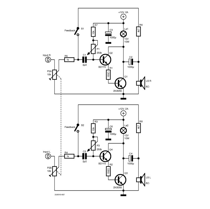
The whole thing was built using home-stocked components, some over-50-year-old Motorola 2N3055s in TO-3 case and a BD115 in TO-39 with gold-plated leads, by Philips, I think. The schematic is shown below in Figure◦1, and its original version was drawn in LTSpice, whose file is available for download in the attachments section here. Although the exact transistor models for BD115 were not available, it did allow for simulating the basic functionality as a first step.
A Darlington configuration creates a sufficiently high input impedance to the signal (music) source; the 2N3055, on its own, has a hfe◦≈◦70 (current amplification), so a base current◦of 1◦mA results in a collector current of approximately 70◦mA. For the full power of 550◦mW in an 8-Ω load, the AC current (peak) will be about 370◦mA, so about 5◦mA AC base current is required for full drive. A value of 5◦mA is a bit on the high side for most (Bluetooth) audio sources.
In the Darlington configuration, the base current for the 2N3055 is delivered by the BD115, and it flows through the main collector load. Hence, the audio source needs to deliver 70 times less current (BD115 has hfe◦=◦70). The resulting 70◦µA can easily be delivered by any audio source. R1 is placed to protect the 2N3055 from over current in its base, and will also linearize the Darlington a bit for a lower distortion.
Another advantage of Darlington is that the DC bias voltage at the base of the BD115 will be the sum of its base-emitter diode and that of the 2N3055, or about:
This is well compatible with the 1◦V to 2◦V RMS output voltage capability of most sources and provides the right amount of input signal amplitude dynamic range.
A simple potentiometer (P1, 250◦kΩ) biases the circuit to provide the minimum base current in the BD115, allowing to play with the set point on the collector of the 2N3055 output stage, bringing it to around 6◦V — or half way the 12◦V supply voltage.
The Lamp
A 12◦V/10◦W halogen lamp (nowadays obsolete and replaced by LEDs) acts as a load for the A-class output stage. The halogen lamp works at half its rated supply voltage, resulting in a current of about 650◦mA and a “cooler operation” in respect to its rated values. A nice side effect is the warmer light glow and the increased lifetime of the lamp itself.
But why a lamp, and not a resistor? Well, the resistor would run quite hot at 3.9◦W and, without giving any visual indication, would be a risk for your fingers! Moreover, the initial Lamp is an important feature of this amplifier.
In fact, the lamp is a positive voltage (rather positive temperature) dependent resistor: at 6◦V it has about 6◦V◦/◦0.65◦A◦=◦9.2◦Ω resistance, where at the rated 12◦V it will show about 14.4◦Ω. This helps to limit the current through the output transistor at high output signal amplitudes. In this case, the 2N3055 is in saturation and only has a voltage drop of about 0.2◦V.
Hence, the lamp effectively protects it against uncontrolled increase in the collector current. An additional advantage will be a softer clipping behavior, which is beneficial for the sound. Don’t try using an LED instead, it simply won’t work!
The signal is applied through a 10◦kΩ audio logarithmic potentiometer, which is in turn connected to RCA inputs to achieve volume control. The slider of the volume pot goes to the base of the BD115, but only after passing through a 2.2◦µF decoupling film◦capacitor. These capacitors separate the DC component (about 2.7◦V) at the BD115 base from the pure AC signal of the audio source.
For the same reason, the loudspeaker is connected in series with a 1000-µF electrolytic decoupling capacitor. A loudspeaker can only work with AC signal and doesn’t tolerate any DC component, that would cause the voice coil to deflect and saturate the magnetic field: an awful event for both the loudspeaker and the sound quality. Not even to mention that a direct current, in this case, would likely heat, and even burn the voice coil.
Feedback
As an additional feature, a feedback switch is foreseen. The R6◦/◦(R5◦+◦Rinput) ratio determines the amount of feedback applied. The output signal is 180° shifted from the input signal. So, by feeding back a small portion of the output signal to the input, we are counteracting the input signal. Amplification will be reduced with this feedback, but in return, we’ll get less distortion and a lower output impedance.
Without feedback the amp will sound louder and more “open”, with feedback it will sound more controlled but less “bright.” We let you judge what you prefer, but in (high-end) tube amps, less feedback is generally considered better by some audio enthusiasts.
Finally, the Lamp Amp needs power. To keep things safe and simple, I used a standard wall-plug type switched-mode power supply that is rated as 12◦V, 2◦A◦DC. Inside the amplifier, additional 2◦×◦1000◦µF capacitors (C3 and C6) act as a local buffer on this 12◦V power supply. A (kill) switch allows to turn off the 12◦V supply.
Practical Realization
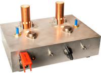
The chosen aluminum chassis was large enough for hosting two identical sections of this circuit, thus realizing a stereo version with independent bias and feedback controls for each channel. The chassis acts as a heat sink for the two 2N3055 power transistors, each dissipating about 6◦V◦×◦0.65◦A◦=◦3.9◦W. A piece of copper tubing effectively protects the lamps from burning fingers and improves the overall look of the design. Make sure to mount the 2N3055 with a mica isolation, as the TO-3 housing is electrically connected to the collector; apply heat dissipating compound on both sides of the mica, to ensure a good thermal transfer. Nylon washers are also needed, to isolate the mounting screws.
The little amplifier has a kind of steampunk-looking. After building it, the first thing we did was to pair it with a Bluetooth player and a set of old loudspeakers. J.J. Cale sounded very relaxed “After Midnight.” The amp was born and played remarkably well and “warm” — no transistor harshness to be spotted.
A little bit of feedback, operated by two switches in the front, allowed us to control the sound from very open to a bit more controlled, depending on the style of music and mood. Since then, we spent hours playing music through the little monster, which is always nice quality time and my perfect excuse to introduce some older music.
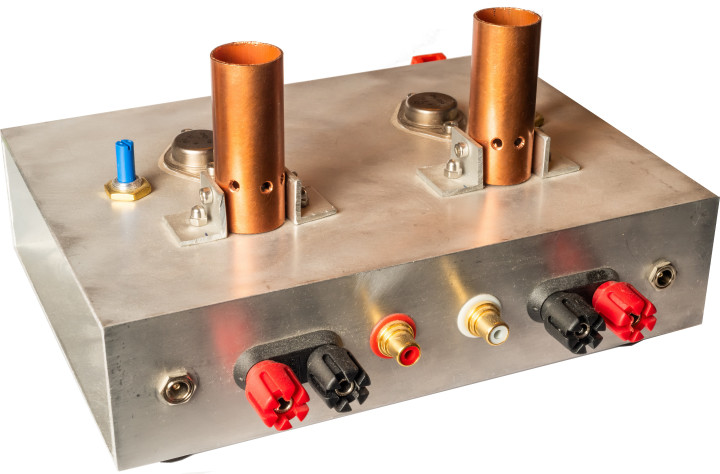
The rear side of the finished prototype is shown in Figure◦2.
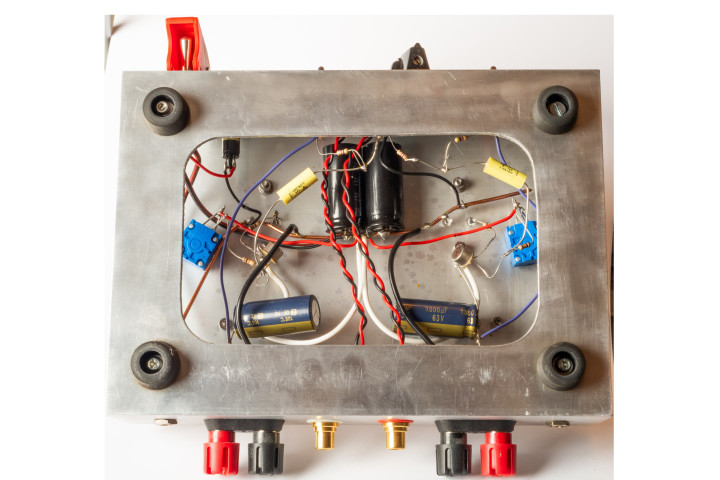
The usage of the old-school point-to-point air wiring eliminated the need for a PCB, as you can see in Figure◦3. A massive 2.5-mm² solid copper wire, anchored to the chassis, works as a ground connection, as well as a mechanical fixation (solder) point for the “floating components.” Input signal wire twisting gives sufficient resilience against external EMI, lowering or avoiding the hum.
Some Measurements
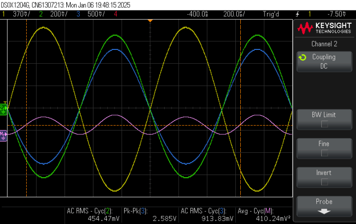
So, what can this little thing do, and what are the specs? Since the engineer in me is difficult to suppress, I performed some late-night measurements using an oscilloscope and build-in waveform generator. The results for a sinewave input signal with and without applying feedback are shown in the following Figure◦4a and Figure4b.
Figure 4a: With Feedback
Figure 4b: Without feedback
The output signal (green) looks almost like a sine wave, too. The slight asymmetry hints 2nd harmonic distortion, but gets better with feedback.
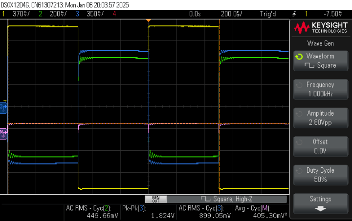
The same setup, but with a square-wave response, is depicted in Figure◦5a and Figure 5b. The response shows slight ringing, which predicts a peak in the Bode plot (frequency response) at high frequency. Feedback doesn’t help here, it only straightens the wave a bit (so less distortion).
Figure 5a: With feedback
Figure 5b: Without Feedback
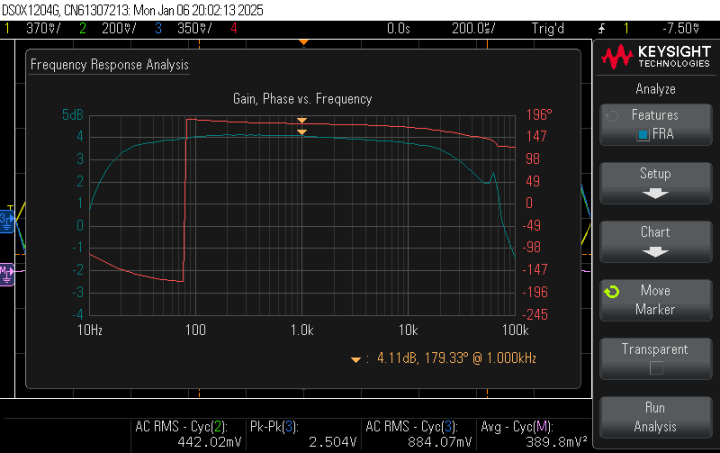
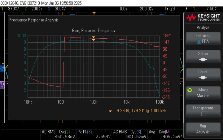
The Bode plot shown in Figure◦6a and Figure 6b is impressive! It improves even with feedback (the phase step of 180° is an artifact of my oscilloscope). The peak at high-frequency is there, but since it’s approx. around 50 to 60◦kHz, it won’t be heard. One can clearly see that feedback improves the frequency response from 35◦Hz...18◦kHz to 17◦Hz...29◦kHz at +/-1dB. A less wanted effect is the reduction of overall gain.
Figure 6a: With feedback
Figure 6b: Without Feedback
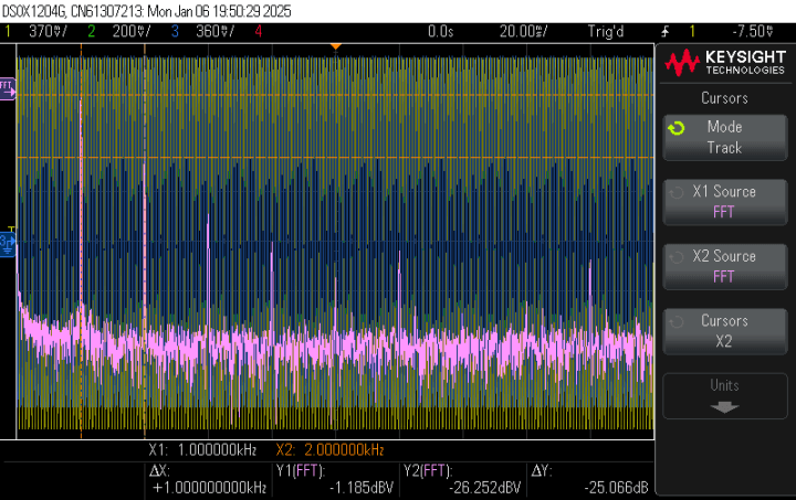
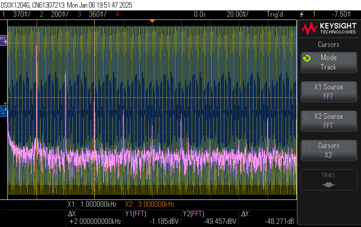
The distortion analysis can be done with the FFT (Fast-Fourrier-Transform) function of the digital oscilloscope. When applying this over sufficient cycles, it gives reasonably accurate results. With no feedback, the FFT result is shown in the following screenshots. A high 2nd◦order (-25◦dB, or 5.6%) (Figure◦7a), but very low 3rd◦order (-49◦dB or 0.35%) (Figure◦7b) harmonics explain the nice “tuby”◦sound.
Figure 7a: Without Feedback
Figure 7b: Without Feedback
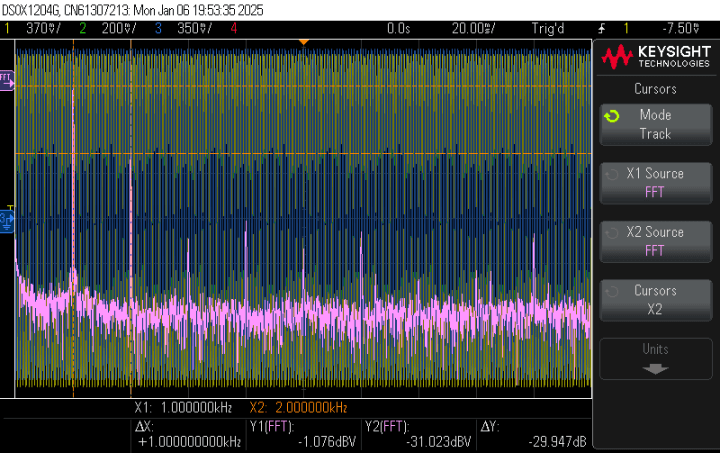
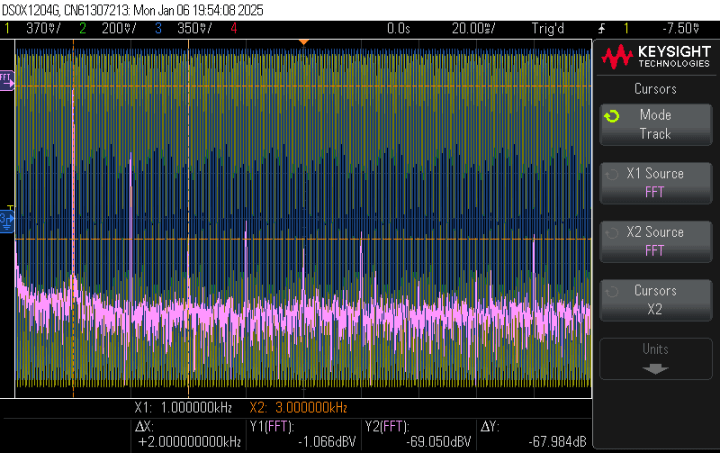
With feedback the FFT results are shown in the following images. Figure 8a shows a lower but still fairly high 2nd order (-30◦dB, or 3.2%), whilst in Figure 8b a very low 3rd order (-68◦dB, or 0.04%) harmonic explains the still nice “tuby”, but less “airy” sound.
Figure 8a: With Feedback
Figure 8b: With Feedback
Finally, I couldn’t resist myself from digging up my audio distortion meter and accompanying low-distortion sine wave generator. This allows an easier measurement of the total harmonic distortion over a wide output power range (1◦mW until 600◦mW clipping level), as shown in the following Figure◦9.
Let It Glow!
This project turned out to be very fun and interesting to carry out, as it involved electronics, mechanics, machining and audio engineering. The kids had lots of fun and were proud of our joint achievement!
The Lamp amplifier seems to me a nice project to explore some basic principles of analog electronics, like resistance, capacitance, amplification, BJTs, biasing, feedback, impedance and so on. Years later, I found some guy who took this subject more seriously, but at the same time, a bit too dangerous for a kids’ project.
Want to build a project?
Bring your design to life with the Elektor PCB Service, powered by Eurocircuits. Upload the project files and order professionally manufactured PCBs or assembled boards through a proven European production platform.
Supporting KiCad, Eagle, Gerber, and ODB++ formats, the service is suitable for everything from prototypes and validation builds to series production and volume manufacturing.
Veuillez saisir votre adresse électronique. Les instructions de réinitialisation de votre mot de passe vous seront immédiatement envoyées par courriel.
Elektor Magazine est depuis 65 ans l’une des principales sources d’information en électronique pour les ingénieurs, les concepteurs, les start-ups et les entreprises. Notre magazine est soutenu par une communauté active d’ingénieurs en électronique – des étudiants aux professionnels – passionnés par la conception et le partage d’idées innovantes.
Pour eux, nous publions chaque année des centaines de contenus sous différents formats, tels que des articles, des vidéos, des webinaires et d’autres formats d’apprentissage. Notre mission est de partager les connaissances de toutes les manières possibles et d’inspirer les lecteurs avec les dernières évolutions du secteur de l’ingénierie électrique.
Thank you for your vote!
Ajoutez vos commentaires
Thank you for your vote!
Veuillez vous connecter pour ajouter une note ou fermez pour revenir en arrière


Discussion (4 commentaire(s))