
Dangerous Jingle Bells at 30kV
Christmas sparkling Jingle Bells using high voltage flyback transformer
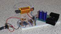
Arduino Pro Mini playing high voltage Jingle Bells tune through the sparks generated by a 30 kV flyback transformer (in fact the high voltage coil is rated for 16 kV, but it can handle voltages that are twice as high). The Arduino Pro mini plays a tune via a digital output that is used to output a PWM output.. To generate the PWM signal the interrupt-based TimerOne library is used. This library is using the 16 bit timer1 of the AVR microcontroller
The firmware contains 2 tunes that can be selected using a digital input pin that is pulled high via the internal pullup of the pin. When the input pin is left open (thus seeing a high level), the "Jingle Bells" tune is played and when the input pin is made low, the "Mission Impossible" tune is played.
The tunes are programmed using lookup tables in which the frequency, the duration and pause times for each note of the tune is stored. The muscial notes are derived from either a midi file or tablature files that can be found on the internet and translated into frequencies,that are output via the digital output that is used to output the PWM signal..
The PWM frequency is changed corresponding to the musical note frequencies. The PWM duty cycle is set fixed to ca. 10%, so the magnetic flux generated by the primary coil of the flyback transformer can build up without saturating the core, formed by the 2 ferrite rods. Especially when playing the lowest frequencies, the current through the primary coil will be higher than when playing the higher frequency notes. This is because the PWM signal uses a fixed duty cycle of 10%. 10% of 100 Hz gives a longer ON-time than 10% of 1000 Hz.. A longer ON-time of the MOSFET causes a higher current flowing through the primary coil, because the current in an inductor will keep on increasing as long as the magnetic core is not getting saturated. With a longer ON-time, the current will raise to higher values than with short ON-times and can cause the magnetic core to get saturated. Saturation of the core means that the magnetic field can not increase any further. When the magnetic field can not increase any further, the current flow is not counteracted anymore and the inductor now acts like a short-circuit, meaning that the current will suddenly raise to a maximum.
The duty cycle of the PWM signal shall not be too low, because then the higher frequencies (shorter ON-times) will cause lower currents in the primary winding and thus lower magnetic flux and less powerful sparks..
The duty cycle shall also not be too high, because then the current through the flyback transformer will become too high with the risk of saturating the magnetic core as explained above.
The frequency of the notes should be in the range of 100's of Hertz because lower frequencies cause more powerful sparks (longer ON-time) and thereby give a higher spark sound volume. Higher frequencies (shorter ON-times) will generate less powerful sparks and thus lower sound levels.
The primary winding of the DIY-flyback transformer is about 20 windings of 0.7mm enamelled copper wire that is wound around one side of 2x 10 mm diameter ferrite rods. The 2 ferrite rods are inserted through the opening of the secondary coil so they stick out at both ends. Due to the low amount of windings, the primary coil has a very low resistance and inductance. The primary winding is controlled by an IRF540 MOSFET and the gate of the MOSFET is connected via a transistor level converter/buffer to the PWM output of the Arduino Pro mini. To store the energy that will be pumped into the primary winding of the flyback transformer by the MOSFET, 2x 6800uF electrolytic capacitors are connected in parallel. These are charged to 12V and buffer the charge that is dumped in the transformer each time the MOSFET conducts.
The secondary coil of the flyback transformer was bought from : https://highvoltageshop.com/epages/b73088c0-9f9a-4230-9ffc-4fd5c619abc4.sf/de_DE/?ObjectPath=/Shops/b73088c0-9f9a-4230-9ffc-4fd5c619abc4/Products/IND_16kV_390m
This 16 kV coil has a inner diameter of 20 mm, so 2x ferrite rods with a diameter of 10 mm just fit inside. This way we can use the ferrite rods to couple the magnetic flux of the primary coil to the secondary coil.
Mises à jour de l'auteur