
DCF77 emulator with ESP8266, Elektor LABS version (150713)
Upgrade your old DCF77 clock to be synchronised via NTP
Here is the original version of this project
Although the idea behind this project is quite straight forward, the implementation is a bit more difficult. The software may need some modification to be compatible with your DCF clock, so we have designed a small PCB in the Elektor lab that makes it very easy to (re)program the ESP8266 module if and when needed.
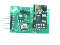
We combined the hardware for the clock and programmer into one circuit and changed the RS232 programming interface to a more modern USB connection. The new schematic consist of the ESP module (MOD1), 3.3V LDO (IC1), a connection for a USB to 3.3V (!!) UART (K1, pin compatible with an FTDI cable), jumper JP1 to set the ESP to programming mode, T1 for buffering/level translation of the DCF output and power LED1. The latter (and R1) may be omitted, the ESP-01 module has its own power LED.
T1 will make interfacing to the hardware of your clock a bit easier, it translates the 3.3V level of the ESP-output to the logic voltage level of your DCF clock. Collector resistor R4 may be omitted if your clock already has a pull-up resistor at the input of the DCF decoder. The DCF output will be inverted by this transistor, we have changed the original software to correct this. You may need to check the documentation of the DCF-module in your clock to see if the output signal should be inverted or not, but you can also use the good-old ‘trial and error’ method to see what polarity of the output works for your clock.
Although many parts are SMD types, soldering and assembling will not be too difficult. In the BOM a 2 x 4-way socket strip is included for mounting the ESP-01 module, but to save space (height) and improve mechanical stability the ESP-01 is preferably soldered on the main PCB without this socket. But you may also remove the socket afterwards.
Before we can use this circuit in the clock, the ESP module must be programmed with the Arduino sketch ESP8266_NTPtoDCF you can download below. If you haven’t programmed any ESP modules before, don’t forget to install the ESP8266 core in the Arduino IDE first. More on this subject can be found on here and on many other internet sites and tutorials.
Before the sketch will work for your DCF clock, there are three things that (may) need modification:
JP1 must be closed at power on to switch the ESP module to flash (programming) mode.
In the Arduino IDE, Tools menu, select ‘Generic ESP8266 Module’ as board type and the correct COM port number of your USB to UART interface. Then compile and upload the sketch, wait for the upload to complete and open the Serial Monitor in the Arduino IDE (again in the Tools menu).
The ESP-module will echo useful information to your computer screen to check if the DCF simulator is doing its job correctly. First it will show if the ESP is able to connect to your network, if not: check if you entered the correct SSID and password in the sketch. After the connection is established, the time server is read and decoded time information is displayed. Please note that the time on your screen is two minutes in advance, this lead is needed to synchronise the DCF clock in time!
If the connection to the time server is not made, you probably misspelled the URL. Correct it in line 65 of the sketch. If you have corrected the sketch you must reprogram the sketch. Remember to power cycle the circuit (unplug and plug K1 again) to put the ESP8266 in programming mode again.
Once the information in the Serial Monitor is correct, the circuit is ready to be installed in your DCF clock. Remove the programming cable from K1 and open jumper JP1. Remove the old DCF receiver from your clock, in most cases it will be a separate module with three wires (+5V, GND and DCF) that connect to K2 of our circuit.
If you want to be sure that the output of our DCF emulator produces a valid DCF code signal, there are numerous Arduino based (test) projects on the internet with DCF77 decoders. We tested our prototype with the DCF77clock_mod sketch
R1 = 220 Ω, thick film, 5%, 0.1W, 150V, 0805
R2 = 47 kΩ, thick film, 5%, 0.1W, 150V, 0805
R3,R4,R5 = 3.3 kΩ, thick film, 5%, 0.1W, 150V, 0805
Capacitor
C1 = 470 nF, 50 V, X7R, 0805
C2 = 100µF, 16V radial can SMD
C3 = 100 nF, 50 V, X7R, 0805
Semiconductor
LED1 = LED, red, 50 mcd, 1.85 V @ 20 mA
T1 = BC847C, 45 V, 100 mA, 250 mW, hfe=400
IC1 = LM3940 3.3V LDO
Other
MOD1 = ESP8266 ESP-01 WiFi module (Elektor shop 150445-91)
K1 = Pin header, breakable, 1 row, 6-way, horizontal
K2 = Pin header, breakable, 1 row, 3-way, vertical
JP1 = Pin header, breakable, 1 row, 2-way, vertical
MOD2 = Pin socket for ESP8266, breakable, 2 rows, 8-way, vertical Jumper, 2 way, 2.54 mm
PCB 150713-1 v1.0
Although the idea behind this project is quite straight forward, the implementation is a bit more difficult. The software may need some modification to be compatible with your DCF clock, so we have designed a small PCB in the Elektor lab that makes it very easy to (re)program the ESP8266 module if and when needed.
We combined the hardware for the clock and programmer into one circuit and changed the RS232 programming interface to a more modern USB connection. The new schematic consist of the ESP module (MOD1), 3.3V LDO (IC1), a connection for a USB to 3.3V (!!) UART (K1, pin compatible with an FTDI cable), jumper JP1 to set the ESP to programming mode, T1 for buffering/level translation of the DCF output and power LED1. The latter (and R1) may be omitted, the ESP-01 module has its own power LED.
T1 will make interfacing to the hardware of your clock a bit easier, it translates the 3.3V level of the ESP-output to the logic voltage level of your DCF clock. Collector resistor R4 may be omitted if your clock already has a pull-up resistor at the input of the DCF decoder. The DCF output will be inverted by this transistor, we have changed the original software to correct this. You may need to check the documentation of the DCF-module in your clock to see if the output signal should be inverted or not, but you can also use the good-old ‘trial and error’ method to see what polarity of the output works for your clock.
Although many parts are SMD types, soldering and assembling will not be too difficult. In the BOM a 2 x 4-way socket strip is included for mounting the ESP-01 module, but to save space (height) and improve mechanical stability the ESP-01 is preferably soldered on the main PCB without this socket. But you may also remove the socket afterwards.
Before we can use this circuit in the clock, the ESP module must be programmed with the Arduino sketch ESP8266_NTPtoDCF you can download below. If you haven’t programmed any ESP modules before, don’t forget to install the ESP8266 core in the Arduino IDE first. More on this subject can be found on here and on many other internet sites and tutorials.
Before the sketch will work for your DCF clock, there are three things that (may) need modification:
- The credentials of your WiFi network
- The URL of the time server used for synchronization
- The polarity of the DCF output
char ssid[] = "your_network_name"; // your network SSID (name)
char pass[] = "network_password"; // your network password
The URL of the NTP time server is defined in line 65:
const char* ntpServerName = "0.nl.pool.ntp.org";
In this case a server for the Dutch (nl) time zone is used. The polarity of the output emulating the DCF coding is defined in lines 462 to 472 of the sketch:
    switch (PartialPulseCount++) {
      case 0:
        if (PulseArray[PulseCount] != 0)
          digitalWrite(LedPin, 0);
        break;
      case 1:
        if (PulseArray[PulseCount] == 1)
          digitalWrite(LedPin, 1);
        break;
      case 2:
        digitalWrite(LedPin, 1);
        break;
For inverted coding (output normally high, pulses zero level) change ‘0’ to ‘1’ and vice versa in the digitalWrite commands. Flashing the ESP8266 NOTE: never connect power to K1 when a USB to serial converter is powering the circuit (or the other way around!) This will short these two 5V power supplies, which results in damage to your DCF clock and/or computer. Close jumper JP1 and connect a 3.3V FTDI cable or any other USB to serial converter between K1 and your computer.JP1 must be closed at power on to switch the ESP module to flash (programming) mode.
In the Arduino IDE, Tools menu, select ‘Generic ESP8266 Module’ as board type and the correct COM port number of your USB to UART interface. Then compile and upload the sketch, wait for the upload to complete and open the Serial Monitor in the Arduino IDE (again in the Tools menu).
The ESP-module will echo useful information to your computer screen to check if the DCF simulator is doing its job correctly. First it will show if the ESP is able to connect to your network, if not: check if you entered the correct SSID and password in the sketch. After the connection is established, the time server is read and decoded time information is displayed. Please note that the time on your screen is two minutes in advance, this lead is needed to synchronise the DCF clock in time!
If the connection to the time server is not made, you probably misspelled the URL. Correct it in line 65 of the sketch. If you have corrected the sketch you must reprogram the sketch. Remember to power cycle the circuit (unplug and plug K1 again) to put the ESP8266 in programming mode again.
Once the information in the Serial Monitor is correct, the circuit is ready to be installed in your DCF clock. Remove the programming cable from K1 and open jumper JP1. Remove the old DCF receiver from your clock, in most cases it will be a separate module with three wires (+5V, GND and DCF) that connect to K2 of our circuit.
If you want to be sure that the output of our DCF emulator produces a valid DCF code signal, there are numerous Arduino based (test) projects on the internet with DCF77 decoders. We tested our prototype with the DCF77clock_mod sketch
BOM 150713
ResistorR1 = 220 Ω, thick film, 5%, 0.1W, 150V, 0805
R2 = 47 kΩ, thick film, 5%, 0.1W, 150V, 0805
R3,R4,R5 = 3.3 kΩ, thick film, 5%, 0.1W, 150V, 0805
Capacitor
C1 = 470 nF, 50 V, X7R, 0805
C2 = 100µF, 16V radial can SMD
C3 = 100 nF, 50 V, X7R, 0805
Semiconductor
LED1 = LED, red, 50 mcd, 1.85 V @ 20 mA
T1 = BC847C, 45 V, 100 mA, 250 mW, hfe=400
IC1 = LM3940 3.3V LDO
Other
MOD1 = ESP8266 ESP-01 WiFi module (Elektor shop 150445-91)
K1 = Pin header, breakable, 1 row, 6-way, horizontal
K2 = Pin header, breakable, 1 row, 3-way, vertical
JP1 = Pin header, breakable, 1 row, 2-way, vertical
MOD2 = Pin socket for ESP8266, breakable, 2 rows, 8-way, vertical Jumper, 2 way, 2.54 mm
PCB 150713-1 v1.0
Discussion (14 commentaire(s))