
ESP32-DAQ, controlling the ESP32 via websockets from a browser
Controlling the ESP32 via websockets from a browser, now with high-speed (up to 1 MSample/s) acqusition modes.
ESP32-DAQ
controlling the ESP32 via websockets from a browser
230115: added high-speed modes for ADC and DAC, see more comments below
When I was a teenager, building electronics was not too expensive, but the peripheral components such boxes, potentiometers, buttons and switches cost a fortune. Nowadays, life is easier, and we control electronics from smart phones and browsers. This triggered the idea to use the ESP32 as a remote-controlled data acquisition system and control it via websockets directly from a browser. Using WiFi makes it even possible to power the ESP32 from a power bank and measure signals without reference to ground potential. The system thus consists of an ESP32, programmed using the Arduino IDE and a HTML5 web page, enhanced with JavaScript, to remotely control the ESP32.
Features
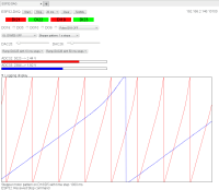
The project image shows the web page with the control panel for the ESP32. In the top row start and stop buttons for the acquisition are located next to an option menu to select the sampling time. I limited the latter to 20 ms update time. You can try to reduce it if you have a fast network. The Clear button is used to reset the scope display below. I also added a TestMe button that I use to try out new features. The IP and port number of the connected ESP32 is displayed on the top right. On the image shown the port number is not 81,as it should be, because the ESP32 was situated on a different network branch and I used port-forwarding. The red and green patches in the second row indicate the state of digital pins 21,22,19, and 23, the first four on the left side of the ESP32. The next row with check-boxes allows to set the output state of digital output pins 18,5,10, and 9. The button to the right allows to continuously toggle pin 18 at a selectable rate. The left button in the row below toggles pin 18 and 5 in an IQ pattern with a 90 degree phase shift. The right button puts a stepper-motor excitation pattern on the four output pins. The sliders in the row below set the output voltage of the two DAC channels on pins 25 an 26 on the right hand side of the ESP32. The buttons below create ramps with a selectable update rate on the DACs. The red and blue horizontal bars indicate the input voltage on ADC channels connected to pins 32 and 33 on the right-hand side of the ESP32, right next to the two DACs The oscilloscope-like display area shows the recorded voltages as a function of time with the selected update rate. When taking the screen shot, I had the DAC and ADC channels connected as well as the corresponding digital output pins connected to the corresponding input pins. And at the same time the digital pins were excited with a stepper motor pattern with a (slow) update rate of once per second. The DACs were performing ramps with different rates that are shown as the sawtooth patterns on the scope display. Note the little arrow next to the "Logging display", which allows to hide the scope display. Below the scope two lines of status information are displayed. The upper shows notes from the web page and the lower, always preceded with "ESP32:" from the ESP32. To make these features work close collaboration of code on the ESP32 and the JavaScript, running in a browser window, is required. Let's look at the ESP32 code first.
ESP32 Software
After defining the WLAN credentials and number of libraries to support WiFi, WebSocketsServer.h to enable support for websockets, esp32-hal.h to support the ESP32 hardware, Ticker.h to control timing, and ArduinoJson.h to support building JSON packages to reliably send data packed in ASCII strings. Then a number of callback functions are defined for data acquisition, ramping the DACs, pulsing digital pin 18, placing the IQ pattern on pins 18 and 5, as well as the stepper-motor excitation pattern. The sendMSG() function packs a JSON package with a text string and signals that it should be transmitted at the next convenient time. The core of the websockets-based communication is in the webSocketEvent() callback function. It is executed if anything to do with websockets happens, either a connection is established or lost, but the most important is the case an ASCII, or text-message of type WStype_TEXT arrives. If that is the case the message is decoded and the elements cmd and val are extracted. Then the code branches, depending on the command "cmd" received. If the message was start, the acquisition is started by attaching the sampleslow_action to the Ticker SampleSlow and the value "val" is interpreted as the sample period. In the same fashion a STOP command detaches the Ticker. The next commands set the DAC on pin 25 and 26 and enable Tickers for the ramping DACs, the IQ modulation and the stepper pattern generator.
In the setup() function first the data direction of the IO pins is defined and the Serial communication enabled, before connecting to the WLAN and finally setting the DACs to zero. The loop() function only calls the webSocket.loop() function to serve and background processes and then checks whether the variable info_available is set, in which case the info buffer, that was filled in the sendMSG() function, is transmitted. If the variable output_ready is set, this happens after acquiring new data in the sampleslow_action() callback function, the samples are stuffed into a JSON package and transmitted to the browser. This is completes the code running on the ESP32. Next we address its counterpart
running in a browser window.
The controlling web page
The web page is called esp32-daq.html and it can be stored anywhere, either on a server but also as a file on the computer on which the browser runs. In a future version, I'll try to configure the ESP32 to host the page itself, but that would clutter the code on the ESP32 even more, and I keep the html page separate for the time being. The top of the HTML page defines the title of the page and the CSS style of several elements, such as their default colors. Then, after the BODY tag, the first row of buttons is defined with the Start, Stop and sample period selection menu. The area containing the input state of the digital input buttons is a on a CANVAS on which I later draw text and place colored rectangles. The next row defines the check-boxes to select the state of the digital output buttons. Note that there is a callback function specified in the onchange directive. These and other callbacks are later defined in the section containing JavaScript at the end of the html file. The following SELECT tag allows to turn on pulsing or toggling pin 18. Likewise, the next to SELECT tags determine the behavior of the IQ and stepper patterns. The two lines starting with DAC25 and DAC26 define the sliders to set the output voltage of the DACs. Again the onchange directive is used to connect a callback function, defined below, to events pertaining to the slider. The following two lines then define canvasses to hold bars indicating the input voltage of the two ADC channels. The section within the tags defines the Logging display with two traces in the SVG display area. Finally, the two status lines are defined.
The section within script tags declares the JavaScript functions that bring the otherwise static web page to live, and interact with the ESP32 in real time. First we define IP address and port number of the connected ESP32. Optionally, the address can be specified in the form esp32-daq.html?ip=192.168.20.100:81 when entering the address of the web page. After opening the connection to the ESP32 in the WebSocket() functions and number of callback functions related to opening, closing and errors are defined. The show_noconnect() function turns off color in the display of the digital output pins to indicate that the acquisition is not running. The function start() and stop() build the JSON strings that are sent to the ESP32 to start and stop the acquisition. Testme() is my playground for new functionality. The most important function is the onmessage() method of the websock. It is called every time a message is received from the ESP32. Inside, it logs the package to the JavaScript console, which is useful for debugging, and then branches according to the type of package received. If it is an INFO message, the contents is shown on the reply line at the bottom of the web page. If it is an ADC package, the text of the item called adc32val is updated with the new values and the colored rectangles are updated for the current ADC values and then the values are appended to the traces on the logging display. If current_position is larger than the horizontal size of the window, the window starts scrolling. This is similar to the roll-mode of some oscilloscopes. The following callback functions are hooked to the corresponding menus and mostly take the selected value, build a JSON string, and transmit it to the ESP32.
When developing the system and playing with it I noticed that linearity of the DAC or the ADC is less than magnificent. On the project image the sawtooth curves bend upwards above 2.5 V. I have not investigated this further, but it indicates that the system cannot substitute a real function generator and a digitizer, but in many projects it may prove useful anyway. For example, the ramping voltages may be useful when setting thresholds for comparators. Or the simple pulse and pattern generators can be used to excite circuits and then use the ADC and digital inputs to sense the response of the circuit. Of course all this only works with rather slow signals. The Ticker library does not support events shorter than 1 ms, but updating to the proper timer libraries will overcome this limit. Moreover, the code is fairly modular such that extending it with additional feature, such as more input channels, both digital and analog, is attractive. Other excitation patterns may also be useful.
I used no external components, but it is easy to envision that adding external ADC or DAC will help to improve the linearity, accuracy, and range of the acquisition. Moreover, the patterns that are generated on the output pins are at nominally 3.3 V. To drive a real stepper motor, either a Darlington or H-bridge driver are needed, as well as, obviously, the motor power supply.
Many other improvements on the hardware side are possible. Feel free to adapt, enhance, and have fun.
Update from 230115 (High-speed modes):
While preparing the second edition of my book "A Hands-on Course in Sensors
Using the Arduino and Raspberry Pi" (Warning: shameless self-advertising!)
I found out that the ESP32, which I also feature in the new edition, supports
a high-speed acquisition mode for its ADC. This mode allows the ESP32 to
sample with honest 200 kSamples/s and even with dishonest 1 MSamples/s
(repeated samples). I thought that this high-speed mode is just too cool not
to include in my "good old ESP32-DAQ" project. So, here is the update that
also includes an adjustable trigger for the high-speed acquisition. The only
thing that is missing is an analog front-end (amplifier, offset control) to
turn this system into an oscilloscope, albeit a rather slow one. I'll have
a look at it, but feel free to contribute.
And there is more: The ESP32 has a built-in frequency generator that feeds
its DACs with samples to produce a few hundred kHz sine waves. I also added
that mode to the ESP32-DAQ. This is rather useful for testing the high-speed
acquisition mode and turns the ESP32 into some sort of function generator,
again, a moderately slow one. You might want to also add a linebuffer op-amp
and maybe some amplitude adjustment. Right now, I only use four built-in
Vpp voltage levels of the ESP32: full, half, quarter, ~1/6 of 3.3 V.
Note also, that as per the previous update the ESP32 hosts the controlling
webpage itself. Just adjust the WLAN credentials to you network and direct
your favorite browser to the IP of the ESP32. It dishes out the webpage
and you're ready to go.
When developing and debugging the system, I had the DAC25 pin connected to
ADC32 and the GPIO pin 18 to ADC33. I also suggest to keep an eye on the
serial output from the ESP32 (115200 baud). It is comforting to see the
communication between the ESP32 and the browser in real time.
Once all is set up, just press "Start" and adjust the DAC25 slider. You
should see the red line reflect the DAC25 setting. Then choose to toggle
pin 18 at a rate of once per second. The blue line should then jump
up and down with one second between jumps.
To change the acquisition rate you must first stop it by pressing "Stop"
and then you can change the update rate from the selection menu at the
top of the webpage before pressing "Start again". The high-speed modes
are further down on the selection menu.
Setting the output frequency and amplitude for the high-speed DAC is done
from the right-most selection menu at the top. You can change that at any
time, even with the acquisition in progress. But in order to see something
sensible you need to choose a high-speed acquisition mode, I'd say at least
200 kSamples/s.
The zip file includes the entire project, both the C code for the ESP32 and
the html webpage including the JavaScript, nothing else is needed. Inspect
and improve! And most of all, have fun!
controlling the ESP32 via websockets from a browser
230115: added high-speed modes for ADC and DAC, see more comments below
When I was a teenager, building electronics was not too expensive, but the peripheral components such boxes, potentiometers, buttons and switches cost a fortune. Nowadays, life is easier, and we control electronics from smart phones and browsers. This triggered the idea to use the ESP32 as a remote-controlled data acquisition system and control it via websockets directly from a browser. Using WiFi makes it even possible to power the ESP32 from a power bank and measure signals without reference to ground potential. The system thus consists of an ESP32, programmed using the Arduino IDE and a HTML5 web page, enhanced with JavaScript, to remotely control the ESP32.
Features
The project image shows the web page with the control panel for the ESP32. In the top row start and stop buttons for the acquisition are located next to an option menu to select the sampling time. I limited the latter to 20 ms update time. You can try to reduce it if you have a fast network. The Clear button is used to reset the scope display below. I also added a TestMe button that I use to try out new features. The IP and port number of the connected ESP32 is displayed on the top right. On the image shown the port number is not 81,as it should be, because the ESP32 was situated on a different network branch and I used port-forwarding. The red and green patches in the second row indicate the state of digital pins 21,22,19, and 23, the first four on the left side of the ESP32. The next row with check-boxes allows to set the output state of digital output pins 18,5,10, and 9. The button to the right allows to continuously toggle pin 18 at a selectable rate. The left button in the row below toggles pin 18 and 5 in an IQ pattern with a 90 degree phase shift. The right button puts a stepper-motor excitation pattern on the four output pins. The sliders in the row below set the output voltage of the two DAC channels on pins 25 an 26 on the right hand side of the ESP32. The buttons below create ramps with a selectable update rate on the DACs. The red and blue horizontal bars indicate the input voltage on ADC channels connected to pins 32 and 33 on the right-hand side of the ESP32, right next to the two DACs The oscilloscope-like display area shows the recorded voltages as a function of time with the selected update rate. When taking the screen shot, I had the DAC and ADC channels connected as well as the corresponding digital output pins connected to the corresponding input pins. And at the same time the digital pins were excited with a stepper motor pattern with a (slow) update rate of once per second. The DACs were performing ramps with different rates that are shown as the sawtooth patterns on the scope display. Note the little arrow next to the "Logging display", which allows to hide the scope display. Below the scope two lines of status information are displayed. The upper shows notes from the web page and the lower, always preceded with "ESP32:" from the ESP32. To make these features work close collaboration of code on the ESP32 and the JavaScript, running in a browser window, is required. Let's look at the ESP32 code first.
ESP32 Software
After defining the WLAN credentials and number of libraries to support WiFi, WebSocketsServer.h to enable support for websockets, esp32-hal.h to support the ESP32 hardware, Ticker.h to control timing, and ArduinoJson.h to support building JSON packages to reliably send data packed in ASCII strings. Then a number of callback functions are defined for data acquisition, ramping the DACs, pulsing digital pin 18, placing the IQ pattern on pins 18 and 5, as well as the stepper-motor excitation pattern. The sendMSG() function packs a JSON package with a text string and signals that it should be transmitted at the next convenient time. The core of the websockets-based communication is in the webSocketEvent() callback function. It is executed if anything to do with websockets happens, either a connection is established or lost, but the most important is the case an ASCII, or text-message of type WStype_TEXT arrives. If that is the case the message is decoded and the elements cmd and val are extracted. Then the code branches, depending on the command "cmd" received. If the message was start, the acquisition is started by attaching the sampleslow_action to the Ticker SampleSlow and the value "val" is interpreted as the sample period. In the same fashion a STOP command detaches the Ticker. The next commands set the DAC on pin 25 and 26 and enable Tickers for the ramping DACs, the IQ modulation and the stepper pattern generator.
In the setup() function first the data direction of the IO pins is defined and the Serial communication enabled, before connecting to the WLAN and finally setting the DACs to zero. The loop() function only calls the webSocket.loop() function to serve and background processes and then checks whether the variable info_available is set, in which case the info buffer, that was filled in the sendMSG() function, is transmitted. If the variable output_ready is set, this happens after acquiring new data in the sampleslow_action() callback function, the samples are stuffed into a JSON package and transmitted to the browser. This is completes the code running on the ESP32. Next we address its counterpart
running in a browser window.
The controlling web page
The web page is called esp32-daq.html and it can be stored anywhere, either on a server but also as a file on the computer on which the browser runs. In a future version, I'll try to configure the ESP32 to host the page itself, but that would clutter the code on the ESP32 even more, and I keep the html page separate for the time being. The top of the HTML page defines the title of the page and the CSS style of several elements, such as their default colors. Then, after the BODY tag, the first row of buttons is defined with the Start, Stop and sample period selection menu. The area containing the input state of the digital input buttons is a on a CANVAS on which I later draw text and place colored rectangles. The next row defines the check-boxes to select the state of the digital output buttons. Note that there is a callback function specified in the onchange directive. These and other callbacks are later defined in the section containing JavaScript at the end of the html file. The following SELECT tag allows to turn on pulsing or toggling pin 18. Likewise, the next to SELECT tags determine the behavior of the IQ and stepper patterns. The two lines starting with DAC25 and DAC26 define the sliders to set the output voltage of the DACs. Again the onchange directive is used to connect a callback function, defined below, to events pertaining to the slider. The following two lines then define canvasses to hold bars indicating the input voltage of the two ADC channels. The section within the tags defines the Logging display with two traces in the SVG display area. Finally, the two status lines are defined.
The section within script tags declares the JavaScript functions that bring the otherwise static web page to live, and interact with the ESP32 in real time. First we define IP address and port number of the connected ESP32. Optionally, the address can be specified in the form esp32-daq.html?ip=192.168.20.100:81 when entering the address of the web page. After opening the connection to the ESP32 in the WebSocket() functions and number of callback functions related to opening, closing and errors are defined. The show_noconnect() function turns off color in the display of the digital output pins to indicate that the acquisition is not running. The function start() and stop() build the JSON strings that are sent to the ESP32 to start and stop the acquisition. Testme() is my playground for new functionality. The most important function is the onmessage() method of the websock. It is called every time a message is received from the ESP32. Inside, it logs the package to the JavaScript console, which is useful for debugging, and then branches according to the type of package received. If it is an INFO message, the contents is shown on the reply line at the bottom of the web page. If it is an ADC package, the text of the item called adc32val is updated with the new values and the colored rectangles are updated for the current ADC values and then the values are appended to the traces on the logging display. If current_position is larger than the horizontal size of the window, the window starts scrolling. This is similar to the roll-mode of some oscilloscopes. The following callback functions are hooked to the corresponding menus and mostly take the selected value, build a JSON string, and transmit it to the ESP32.
When developing the system and playing with it I noticed that linearity of the DAC or the ADC is less than magnificent. On the project image the sawtooth curves bend upwards above 2.5 V. I have not investigated this further, but it indicates that the system cannot substitute a real function generator and a digitizer, but in many projects it may prove useful anyway. For example, the ramping voltages may be useful when setting thresholds for comparators. Or the simple pulse and pattern generators can be used to excite circuits and then use the ADC and digital inputs to sense the response of the circuit. Of course all this only works with rather slow signals. The Ticker library does not support events shorter than 1 ms, but updating to the proper timer libraries will overcome this limit. Moreover, the code is fairly modular such that extending it with additional feature, such as more input channels, both digital and analog, is attractive. Other excitation patterns may also be useful.
I used no external components, but it is easy to envision that adding external ADC or DAC will help to improve the linearity, accuracy, and range of the acquisition. Moreover, the patterns that are generated on the output pins are at nominally 3.3 V. To drive a real stepper motor, either a Darlington or H-bridge driver are needed, as well as, obviously, the motor power supply.
Many other improvements on the hardware side are possible. Feel free to adapt, enhance, and have fun.
Update from 230115 (High-speed modes):
While preparing the second edition of my book "A Hands-on Course in Sensors
Using the Arduino and Raspberry Pi" (Warning: shameless self-advertising!)
I found out that the ESP32, which I also feature in the new edition, supports
a high-speed acquisition mode for its ADC. This mode allows the ESP32 to
sample with honest 200 kSamples/s and even with dishonest 1 MSamples/s
(repeated samples). I thought that this high-speed mode is just too cool not
to include in my "good old ESP32-DAQ" project. So, here is the update that
also includes an adjustable trigger for the high-speed acquisition. The only
thing that is missing is an analog front-end (amplifier, offset control) to
turn this system into an oscilloscope, albeit a rather slow one. I'll have
a look at it, but feel free to contribute.
And there is more: The ESP32 has a built-in frequency generator that feeds
its DACs with samples to produce a few hundred kHz sine waves. I also added
that mode to the ESP32-DAQ. This is rather useful for testing the high-speed
acquisition mode and turns the ESP32 into some sort of function generator,
again, a moderately slow one. You might want to also add a linebuffer op-amp
and maybe some amplitude adjustment. Right now, I only use four built-in
Vpp voltage levels of the ESP32: full, half, quarter, ~1/6 of 3.3 V.
Note also, that as per the previous update the ESP32 hosts the controlling
webpage itself. Just adjust the WLAN credentials to you network and direct
your favorite browser to the IP of the ESP32. It dishes out the webpage
and you're ready to go.
When developing and debugging the system, I had the DAC25 pin connected to
ADC32 and the GPIO pin 18 to ADC33. I also suggest to keep an eye on the
serial output from the ESP32 (115200 baud). It is comforting to see the
communication between the ESP32 and the browser in real time.
Once all is set up, just press "Start" and adjust the DAC25 slider. You
should see the red line reflect the DAC25 setting. Then choose to toggle
pin 18 at a rate of once per second. The blue line should then jump
up and down with one second between jumps.
To change the acquisition rate you must first stop it by pressing "Stop"
and then you can change the update rate from the selection menu at the
top of the webpage before pressing "Start again". The high-speed modes
are further down on the selection menu.
Setting the output frequency and amplitude for the high-speed DAC is done
from the right-most selection menu at the top. You can change that at any
time, even with the acquisition in progress. But in order to see something
sensible you need to choose a high-speed acquisition mode, I'd say at least
200 kSamples/s.
The zip file includes the entire project, both the C code for the ESP32 and
the html webpage including the JavaScript, nothing else is needed. Inspect
and improve! And most of all, have fun!
Mises à jour de l'auteur