
Frost Guard and Temperature Data Logger
Every spring time I admire the flowering of the fruit trees in my garden. The first to flourish is an apricot tree. So early (begin of march this year) that the March and April frost in the past years destroyed all harvest. Fruit farmers utilize the heat of crystallization when water freezes below 4° C. So I decided to irrigate my apricot tree to avoid frost destruction.
=> Advanced version with ATtiny84 controller (see "Updates" at the end of the article)
Commercial frost guard systems are quite expensive. Not the watering part but the controller part. My self-made solution consists of
Frost Guard controller features
The frost guard controller has two main operation modes.
Main mode watch
In watch mode the temperature is monitored all 10[s]. If the temperature reaches the low threshold temperature (adjustable, default 1° C) the irrigation starts. Irrigation stops if the temperature raises above the high threshold temperature (adjustable, default 3° C). When the temperature raises above the low threshold temperature the irrigation is pulsed. For each 0.5 °C temperature increase a 30[s] pause is inserted after 60[s] of irrigation
.
Each irrigation event is recorded with a time stamp and the corresponding temperature. The recorded data is written into the controller’s eeprom memory (until it’s full: 83 events). Data is dumped @19200 Baud in an ascii JSON pretty print format utilizing a mobile phone with a USB terminal software[2], a USB OTG adapter and an FT232RL USB to TTL serial adapter[3] (see attachment file serial-adapter.jpg).
Main mode menu
The menu comprises selection of modes:
The different modes are explained in the project documentation (see attachment file FrostGuard.pdf).
Hardware
The hardware is simple state of the art (see attachment file frostguard-schem.png):
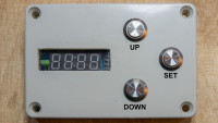
The prototype is housed in a IP65 protected module box sized 100 mm x 68 mm x 50 mm. The display is mounted to a 5mm plexiglass epoxied to the module box front. Left of the 7 segments display the irrigation control LED is positioned.
Three push buttons are connected to the TM1637 keyboard interface. The utilized display from az-delivery[5] does not support keyboard input, so I had to pimp the display. A 4 pins male connector is epoxied to the display pcb supplying keyboard connectors K1, KS2, KS2 and KS3 (see attachment file pimped-tm1637.jpg).
The temperature sensor needs a 15 meters cable. Available pre confectioned sensors do have a maximum of 10 meters cable. Coax cables with BNS connectors of 15 meters length are available for less than 10 EURO. Resulting a two wires connection for the temperature sensor (see data sheet[6], page 7, parasite power mode) was chosen. The sensor is epoxied into a 6mm Ø aluminum tube and hence is water proof (see attachment file temp-sensor-real.png).
I’ve seen a lot of discussions in the web about possible cable lengths for the temperature sensor. I agree it’s a matter of controller timing on the one hand and a matter of reflections in a long cable on the other. The sensor software uses bit banging with some µs timing. Hence the power up of the sensor running in parasite power mode is important. This is reflecting in file module_watch.c.
The prototype module box has three connectors:
The external power supply is adjusted to the irrigation water valve operation voltage of 24 VAC. Vcc for the microcontroller logic is generated by a 4 x 1N4001 bridge rectifier with 220µF capacitor and an az-delivery LM2596S DC-DC step down module[8] (see attachment file protoype-inside.jpg).
BOM
C1 100nF
C2 100µF
D1 1N4148
D2 LED - optical irrigation control
J1 Conn_01x02_Male - power supply
J2 Conn_01x02_Male - temperature sensor
J3 Conn_01x02_Male - irrigation valve
K1 ZETTLER-AZ943
Q1 BC559
Q2 BC559
R1 10k
R2 4k7
R3 6k8
R4 47
SW1 UP – pushbutton
SW2 DOWN – pushbutton
SW3 SET – pushbutton
U1 ATtiny85-20PU
U2 az-delivery 4 Digit 7 Segment Display [5]
U3 DS18S20 temperature sensor [6]
Placement of components see attachment file prototype-pcb.jpg.
The three pins male connector located below the Attiny85 socket are test pins (right to left) for GND, sensor parasite power and sensor DIO.
Software
The software is set up as a state machine - see attachment file state-machine.png.
On initial reset, when date and time as well as threshold temperature values are unset, the state machine executes date/time setting and threshold temperature setting before it enters the watch state.
As shown in the hardware section (attachment file module-box-front.jpg) there are three push buttons available for the user interface: UP, DOWN and SET
The state machine is controlled by a 100[ms] period timer interrupt. The timer interrupt and some more
initializations are performed in the main() function finally going to sleep in sleep mode IDLE (see [4] page 34, Sleep Modes).
The timer interrupt service routine has several roles:
Each mode function is called by the mode dispatcher passing the current key code as argument and returns from execution within the 100[ms] period.
The mode dispatcher is controlled by globals.mode variable. Any mode function may manipulate the variable globals.mode. Within each mode function the different states of a mode function is reflected in a variable globals.submode. On globals.submode == SUBMODE_EXIT any mode function does set the globals.mode variable to the next mode and clears the globals.submode variable.
None of the mode functions has any loop construction. All loop-alike constructions are realized as counters depending on the 100[ms] timer interrupt period. No polling loops are implemented.
File list (all in attachment file FrostGuard.pdf):
Let’s have a look at some of the source code files.
The temperature sensor code resides in files ds18x20.h and ds18x20.c. It’s taken from Davide Gironi. My modifications are related to support both DS18B20 and DS18S20 sensor types.
File ds18x20.h contains the sensor type definition for my project:
File ds18x20.h further defines the sensor functions, sensor macros (sensor type dependent), some specific return value and sensor commands.
Davide’s original sensor lib provides one function for temperature sensor request:
This function starts the temperature conversion and then polls for the “ready” signal of the sensor. Next it reads and returns the sensor data. This is a synchronous mode of retrieving the sensor data. Which is not applicable in my project (no poll loops).
For asynchronous retrieval of temperature sensor data the function DS18x20_gettemp() is split up in an initialization part (function DS18x20_startcv()) and a sensor data retrieval part (function DS18x20_readtemp()). To distinguish from successful operation and failure there are specific return values defined in file ds18x20.h:
The code calling functions DS18x20_startcv() and DS18x20_readtemp() must comply to the conversion times between calling the two functions. Conversion times are taken from the DS18B20 / DS18S20 data sheets [6, 7] and defined depending on sensor type and sensor resolution (all in [ms]):
The conversion time is defined in file frostguard.h as all other time constants are.
CONVERSION_TIME is aligned to the 100[ms] system tick.
Modes are defined as bit vector values so the code does not need to combine multiple if requests when there is defined an operation for multiple modes.
Each mode function returns a mode status value telling the mode dispatcher if there is some wrap up to perform (see end of timer interrupt service routine in file frostguard.c).
Key scanning in the timer interrupt service routine supplies one of the key codes:
The display may have one of three different states:
Irrigation is controlled by Port B pin 2 and R3 / Q2 / K1:
The display can operate in eight brightness steps:
According to the resolution of 0.5[°] the binary representation is calculated:
File globals.h defines the data types used in all global variables.
Date and time format is the Unix based timestamp. Initial value is 2021-04-05 12:00:00.
Each irrigation event is recorded. An irrigation event is defined as the change of irrigation mode from 0 (no irrigation) to 1 (permanent irrigation), 2 or more and back to 0. To each irrigation event the time and (binary) temperature is recorded.
All global variables are stored in a structure containing the runtime parameters, mode and submode value as well as display status values.
All messages shown in the display are defined here. The corresponding binary values are defined in file globals.c. If you want to modify the code, please keep the menu entries in the original order as the first ones. They correspond to a mode array in file mode_menu.c.
With a little bit of phantasy, it is possible to display all the message words with a seven segments display (see attachment file messages.png).
The EEPROM of the ATTiny85 controller is used to store the program parameters and the recorded irrigation events. The number of irrigation events is limited by the EEPROM data size. It’s taken from the E2END constant from include file avr/eeprom.h.
File globals.c holds the globals, the EEPROM data and the message binary codes array.
Next let’s have a look at the menu mode function defined in file mode_menu.c. As shown at the beginning of the Software section the menu mode lets the user select between different functionalities:
The variable globals.submode is used to hold the selected menu item. It is modified by keys UP or DOWN. On SET key the selected mode is set into variable globals.mode, globals.submode cleared and MDS_DONE returned. On the next timer interrupt the mode dispatcher calls the mode function corresponding to the selected mode.
Please note the “round robin” feature of menu items:
Such you’ll find in other mode files evaluating keys UP and DOWN. As an example, let’s look at file mode_temp.c.
Submode 0 is used to set up this function. The display shows a leading “H” (for High threshold temperature) and the currently set high threshold temperature. Next the submode is set to 1.
On the next execution of this function the current key code is evaluated. On key UP/DOWN the display blinking stops and the high threshold temperature value is increased/decreased within the limits of 0[°C] <= high temp <= 20[°C] in 0.5° steps (as this is the temperature sensor resolution). In this function there is no “round robin” implemented for the threshold temperatures settings. On key SET the submode is increased to 2.
Submode 2 shows the current low threshold temperature with a leading “L” in the display, blinking, and sets the submode to 3.
On the next execution of this function again the current key code is evaluated. On key UP/DOWN the display blinking stops and the low threshold temperature value is increased/decreased within the limits of 0[°C] <= high temp <= 20[°C] in 0.5° (again no “round robin”). On key SET the submode is set to SUBMODE_EXIT.
On the next execution this function performs all wrap up.
Similar functionality is given by the mode functions in files mode_datetime.c, mode_brightness.c and mode_irrigate.c.
The file mode_data.c holds the mode function for the data transfer. Data is dumped @19200 Baud in an ascii JSON pretty print format, good for human reading and interpretation.
Here’s an excerpt of logged data transfer from 2021-04-09.
Members “tH” and “tL” represent the threshold temperature parameters.
Members “mH” and “mL” represent the measured maximum and minimum temperatures.
The irrigation event data is transferred in an array. Each array entry has the members
Event data shows
The data transfer utilizes the serial to TTL functions uart_tx() and uart_tx_string() in file uart.c.
The base function uart_tx() uses bit-banging at 19.200 Baud having 52,1[µs] bit time.
The delay times are adjusted to the 52,1[µs] bit time. In real the bit time is 52[µs], which is close enough to operate at a wide temperature range on data transfer. My first implementation was at 57.600 Baud having 17,4[µs] bit time. This worked fine in my heated dev shack but was unreliable at low temperatures in my unheated garden cabin.
Eventually let’s have a look at file mode_watch.c containing the watch mode workhorse function.
The function has the three sub modes 0 (for initialization), SUBMODE_EXIT (for exit wrap up) and 1 (for regular operation).
On key SET hit the last sampled temperature is displayed. Display time is controlled by a counter variable “display”. On value zero the display is off. On values 1 to TEN_SECONDS the display is on.
The measure (sample) cycle is controlled by a counter variable “measure_count” having initial value zero. On value 0 the temperature sensor is powered up (parasite power mode!) by setting DS18x20_PWRON(). After 2 cycles (value of measure_count is 2) the parasite power is set off and the conversion started. After CONVERSION_TIME + 2 cycles the sensor value is picked and (in case of a meaningful value) the irrigation mode is calculated.
From the calculated irrigation mode, the pulse irrigation is controlled by a variable “pulse_timer” (initial value: 0) and an irrigation variable “irri_timer” (initial value: 0).
The variable “irri_timer” is the timer counter for the irrigation and pause phases, set if value 0:
The variable “puls_timer” reflects the irrigation mode:
By this the pulse irrigation is controlled by irrigation mode:
User manual
The project documentation in attachment file FrostGuard.pdf contains a brief user manual section.
References
[1] Circular sprinkler
https://www.amazon.de/-/en/Circular-sprinkler-different-surfaces-securely/dp/B086FWFNRX?th=1
[2] Android USB terminal software
https://play.google.com/store/apps/details?id=de.kai_morich.serial_usb_terminal
[3] FT232RL USB to TTL serial adapter
https://www.az-delivery.de/en/products/ftdi-adapter-ft232rl
[4] Atmel ATtiny25, ATtiny45, ATtiny85 Datasheet
https://ww1.microchip.com/downloads/en/DeviceDoc/Atmel-2586-AVR-8-bit-Microcontroller-ATtiny25-ATtiny45-ATtiny85_Datasheet.pdf
[5] 7 segments 4 digits display from az-delivery
https://www.az-delivery.de/en/collections/displays/products/4-digit-display
[6] DS18S20 temperature sensor data sheet
https://datasheets.maximintegrated.com/en/ds/DS18S20.pdf
[7] DS18B20 temperature sensor data sheet
https://datasheets.maximintegrated.com/en/ds/DS18B20.pdf
[8] az-delivery LM2596S DC-DC step down module
https://www.az-delivery.de/en/products/lm2596s-dc-dc-step-down-modul-1
Commercial frost guard systems are quite expensive. Not the watering part but the controller part. My self-made solution consists of
- the AVR ATTiny-85 basedFrost Guard controller
- a valve to switch irrigation on and off
- a circular sprinkler[1] and some meters of hose
Frost Guard controller features
The frost guard controller has two main operation modes.
Main mode watch
In watch mode the temperature is monitored all 10[s]. If the temperature reaches the low threshold temperature (adjustable, default 1° C) the irrigation starts. Irrigation stops if the temperature raises above the high threshold temperature (adjustable, default 3° C). When the temperature raises above the low threshold temperature the irrigation is pulsed. For each 0.5 °C temperature increase a 30[s] pause is inserted after 60[s] of irrigation
.
Each irrigation event is recorded with a time stamp and the corresponding temperature. The recorded data is written into the controller’s eeprom memory (until it’s full: 83 events). Data is dumped @19200 Baud in an ascii JSON pretty print format utilizing a mobile phone with a USB terminal software[2], a USB OTG adapter and an FT232RL USB to TTL serial adapter[3] (see attachment file serial-adapter.jpg).
Main mode menu
The menu comprises selection of modes:
- Date and time setup
- Threshold temperatures setup
- Brightness setup
- Irrigation on/off (for tests)
- Data transfer
The different modes are explained in the project documentation (see attachment file FrostGuard.pdf).
Hardware
The hardware is simple state of the art (see attachment file frostguard-schem.png):
- an ATTiny85 micro controller [4]
- a TM1637 controlled 4 digits 7 segments display [5]
- a DS18S20 temperature sensor [6]
- the TM1637 is also utilized to interface 3 push buttons
- a 5V relay for irrigation control
The prototype is housed in a IP65 protected module box sized 100 mm x 68 mm x 50 mm. The display is mounted to a 5mm plexiglass epoxied to the module box front. Left of the 7 segments display the irrigation control LED is positioned.
Three push buttons are connected to the TM1637 keyboard interface. The utilized display from az-delivery[5] does not support keyboard input, so I had to pimp the display. A 4 pins male connector is epoxied to the display pcb supplying keyboard connectors K1, KS2, KS2 and KS3 (see attachment file pimped-tm1637.jpg).
The temperature sensor needs a 15 meters cable. Available pre confectioned sensors do have a maximum of 10 meters cable. Coax cables with BNS connectors of 15 meters length are available for less than 10 EURO. Resulting a two wires connection for the temperature sensor (see data sheet[6], page 7, parasite power mode) was chosen. The sensor is epoxied into a 6mm Ø aluminum tube and hence is water proof (see attachment file temp-sensor-real.png).
I’ve seen a lot of discussions in the web about possible cable lengths for the temperature sensor. I agree it’s a matter of controller timing on the one hand and a matter of reflections in a long cable on the other. The sensor software uses bit banging with some µs timing. Hence the power up of the sensor running in parasite power mode is important. This is reflecting in file module_watch.c.
The prototype module box has three connectors:
- BNC connector for temperature sensor and serial data
- Power supply connector
- Irrigation valve connector
The external power supply is adjusted to the irrigation water valve operation voltage of 24 VAC. Vcc for the microcontroller logic is generated by a 4 x 1N4001 bridge rectifier with 220µF capacitor and an az-delivery LM2596S DC-DC step down module[8] (see attachment file protoype-inside.jpg).
BOM
C1 100nF
C2 100µF
D1 1N4148
D2 LED - optical irrigation control
J1 Conn_01x02_Male - power supply
J2 Conn_01x02_Male - temperature sensor
J3 Conn_01x02_Male - irrigation valve
K1 ZETTLER-AZ943
Q1 BC559
Q2 BC559
R1 10k
R2 4k7
R3 6k8
R4 47
SW1 UP – pushbutton
SW2 DOWN – pushbutton
SW3 SET – pushbutton
U1 ATtiny85-20PU
U2 az-delivery 4 Digit 7 Segment Display [5]
U3 DS18S20 temperature sensor [6]
Placement of components see attachment file prototype-pcb.jpg.
The three pins male connector located below the Attiny85 socket are test pins (right to left) for GND, sensor parasite power and sensor DIO.
Software
The software is set up as a state machine - see attachment file state-machine.png.
On initial reset, when date and time as well as threshold temperature values are unset, the state machine executes date/time setting and threshold temperature setting before it enters the watch state.
As shown in the hardware section (attachment file module-box-front.jpg) there are three push buttons available for the user interface: UP, DOWN and SET
- Push UP or DOWN button to step through the available options
- Push SET button to select an option or to show current temperature in watch mode
- Long push SET button
- to interrupt menu mode or any sub mode to return to watch mode
- to interrupt watch mode to get to menu mode
The state machine is controlled by a 100[ms] period timer interrupt. The timer interrupt and some more
initializations are performed in the main() function finally going to sleep in sleep mode IDLE (see [4] page 34, Sleep Modes).
The timer interrupt service routine has several roles:
- scan push button input (key)
- 400[ms] period display blink function
- 1000[ms] period time stamp ticker
- mode dispatcher
Each mode function is called by the mode dispatcher passing the current key code as argument and returns from execution within the 100[ms] period.
The mode dispatcher is controlled by globals.mode variable. Any mode function may manipulate the variable globals.mode. Within each mode function the different states of a mode function is reflected in a variable globals.submode. On globals.submode == SUBMODE_EXIT any mode function does set the globals.mode variable to the next mode and clears the globals.submode variable.
None of the mode functions has any loop construction. All loop-alike constructions are realized as counters depending on the 100[ms] timer interrupt period. No polling loops are implemented.
File list (all in attachment file FrostGuard.pdf):
- frostguard.c / frostguard.h main() function and major definitions
- globals.c / globals.h global variables
- mode_brightness.c mode for brightness control
- mode_data.c mode for data transfer
- mode_datetime.c mode for date and time setting
- mode_irrigate.c mode for irrigation test
- mode_menu.c menu mode
- mode_temp.c mode for threshold temperatures setting
- mode_watch.c watch mode
- ds18x20.c / ds18x20.h temperature sensor control
- tm1637.c / tm1637.h display and push buttons control
- uart.c / uart.h serial TTL output control
Let’s have a look at some of the source code files.
The temperature sensor code resides in files ds18x20.h and ds18x20.c. It’s taken from Davide Gironi. My modifications are related to support both DS18B20 and DS18S20 sensor types.
File ds18x20.h contains the sensor type definition for my project:
/* ----------------- sensor definition section -----------------
*
* Type of sensor - set to DS18B10 or DS18S10
*/
#define DS18x20_TYPE DS18S10
/*
* Sensor resolution - set to 9, 10, 11 or 12 for DS18B20
* (no effect for DS18S20)
*/
#define DS18x20_RESOL 9
/*
* Operation mode - set to
* - 0 for no parasite-powered operation
* - 1 for parasite-power on output high
* - 2 for parasite-power on output low
*/
#define DS18x20_PARAPWR 2
/*
* connection setup
*/
#define DS18x20_PORT PORTB
#define DS18x20_DDR DDRB
#define DS18x20_PIN PINB
#define DS18x20_PWR PB4
#define DS18x20_DQ PB3
File ds18x20.h further defines the sensor functions, sensor macros (sensor type dependent), some specific return value and sensor commands.
Davide’s original sensor lib provides one function for temperature sensor request:
int16_t DS18x20_gettemp();
This function starts the temperature conversion and then polls for the “ready” signal of the sensor. Next it reads and returns the sensor data. This is a synchronous mode of retrieving the sensor data. Which is not applicable in my project (no poll loops).
For asynchronous retrieval of temperature sensor data the function DS18x20_gettemp() is split up in an initialization part (function DS18x20_startcv()) and a sensor data retrieval part (function DS18x20_readtemp()). To distinguish from successful operation and failure there are specific return values defined in file ds18x20.h:
/*
 * return values (int16_t)
 *
 * 0x07D0...0xFC90 -> +125[°]...-55[°] on 12 Bit resolution
 * 0x00AA...0xFF92 ->  +85[°]...-55[°] on  9 Bit resolution
 */
#define DS18x20_NO_VALUE     (DS18x20_MAX + 1)   // ok - no value sampled
#define DS18x20_NO_RESET     (DS18x20_MAX + 2)   // error - no sensor reset
#define DS18x20_NO_DATA      (DS18x20_MAX + 3)   // error - no sensor data
The code calling functions DS18x20_startcv() and DS18x20_readtemp() must comply to the conversion times between calling the two functions. Conversion times are taken from the DS18B20 / DS18S20 data sheets [6, 7] and defined depending on sensor type and sensor resolution (all in [ms]):
#if DS18x20_TYPE == DS18S10
#  define DS18x20_CVT 750
#else
#  if DS18x20_RESOL == 9
#    define DS18x20_CVT 94
#  endif
#  if DS18x20_RESOL == 10
#    define DS18x20_CVT 188
#  endif
#  if DS18x20_RESOL == 11
#    define DS18x20_CVT 375
#  endif
#  if DS18x20_RESOL == 12
#    define DS18x20_CVT 750
#  endif
#endif // DS18x20__TYPE == DS18S10
The conversion time is defined in file frostguard.h as all other time constants are.
CONVERSION_TIME is aligned to the 100[ms] system tick.
/**
 * timer ISR(TIM0_COMPA_vect)@100[ms] related stuff
 */
#define CONVERSION_TIME (((DS18x20_CVT / 100) * 100) < DS18x20_CVT \
   ? (DS18x20_CVT / 100) + 1 \
   : (DS18x20_CVT / 100))

#define ONE_SECOND    10
#define TEN_SECONDS   100
#define THIRTY_SECONDS 300
#define SIXTY_SECONDS 600
Modes are defined as bit vector values so the code does not need to combine multiple if requests when there is defined an operation for multiple modes.
/**
 * modes of the state machine
 */
#define MODE_UNSET    0 // no mode set
#define MODE_RESET  _BV(0)  // power on
#define MODE_TEMPS  _BV(1)  // set temperatures
#define MODE_DATIME _BV(2)  // set date/time
#define MODE_WATCH  _BV(3)  // watch temperature
#define MODE_MENU   _BV(4)  // menu
#define MODE_IRRIG  _BV(5)  // manual irrigation
#define MODE_BRIGHT _BV(6)  // set brightness
#define MODE_DATA   _BV(7)  // retrieve irrigation data

#define SUBMODE_EXIT   99    // submode: exit mode
Each mode function returns a mode status value telling the mode dispatcher if there is some wrap up to perform (see end of timer interrupt service routine in file frostguard.c).
/*
 * mode function status return codes
 */
#define MDS_RUN     0
#define MDS_DONE    1
Key scanning in the timer interrupt service routine supplies one of the key codes:
/**
 * key codes from TM1637_keyscan()
 */
#define KEY_NONE     0xFF    // all keys released
#define KEY_UP      0x07    // key UP hit
#define KEY_DOWN     0x06    // key DOWN hit
#define KEY_SET     0x05    // key SET hit
#define KEY_UP_L     0x77    // key UP long hold
#define KEY_DOWN_L  0x66    // key DOWN long hold
#define KEY_SET_L   0x55    // key SET long hold
The display may have one of three different states:
/**
 * display status
 */
#define DSP_OFF     0
#define DSP_ON      1
#define DSP_BLINK   2
Irrigation is controlled by Port B pin 2 and R3 / Q2 / K1:
/**
 * port B pin 2 used for irrigation relay control (low = on)
 */
#define IRRI_INIT() (DDRB |= _BV(DDB2))
#define IRRI_ON()   (PORTB &= ~_BV(PB2))
#define IRRI_OFF()  (PORTB |= _BV(PB2))
The display can operate in eight brightness steps:
/**
 * brightness (0...TM1637_BRIGHTNESS_MAX)
 */
#define DEFAULT_BRIGHTNESS  5
#define MAX_BRIGHTNESS      7
According to the resolution of 0.5[°] the binary representation is calculated:
/**
 * binary temperature (0.5[°] resolution)
 */
#define BINTEMP(x)  (x * 2)
File globals.h defines the data types used in all global variables.
typedef struct
{
    int8_t  low;
    int8_t  high;

} temperatures_t;

typedef struct params   // runtime parameters / copy in eeprom
{
    temperatures_t  temperatures;   // threshold temperatures
    temperatures_t  minmax;         // min/max temperatures
    uint32_t        timestamp;      // reference January 1st 1970 00:00:00 in [s]
    uint8_t         brightness;
    int8_t          write;          // event data eeprom write index

} params_t;
Date and time format is the Unix based timestamp. Initial value is 2021-04-05 12:00:00.
#define DT_2021_4_5_12_0_0 ((((uint32_t)(2021 - 1970) * 365 \
    + (uint32_t)((2021 - 1968) / 4) + (31 + 28 + 31 + 3)) * 24 + 12) * 60 * 60)
Each irrigation event is recorded. An irrigation event is defined as the change of irrigation mode from 0 (no irrigation) to 1 (permanent irrigation), 2 or more and back to 0. To each irrigation event the time and (binary) temperature is recorded.
typedef struct      // irrigation event data
{
    uint32_t    timestamp;  // 1[s] resolution timestamp since 1970-01-01 00:00:00
    int8_t      temp;       // binary temperature 0.5[°] resolution
    uint8_t     irri_mode;  // irrigation mode

} event_t;
All global variables are stored in a structure containing the runtime parameters, mode and submode value as well as display status values.
/**
 * globals
 */
typedef struct
{
    params_t     params;
    uint8_t     mode;
    uint8_t     submode;
    uint8_t     blinker;
    uint8_t     col_stat;   // colon status off/on/blinking
    uint8_t     dsp_stat;   // display status off/on/blinking

} globals_t;

extern globals_t globals;
All messages shown in the display are defined here. The corresponding binary values are defined in file globals.c. If you want to modify the code, please keep the menu entries in the original order as the first ones. They correspond to a mode array in file mode_menu.c.
/**
 * display messages for menus et.al.
 */
extern const uint8_t messages[];
// menu messages definitions - keep at begin and in order (see mode_menu.c)
#define MSG_dAtA     ((uint8_t *)(messages +  0))
#define MSG_irri     ((uint8_t *)(messages +  4))
#define MSG_bri      ((uint8_t *)(messages +  8))
#define MSG_tEnP     ((uint8_t *)(messages + 12))
#define MSG_dAtE     ((uint8_t *)(messages + 16))
// end of menu messages - other messages
#define MSG_SEnd     ((uint8_t *)(messages + 20))
#define MSG_on       ((uint8_t *)(messages + 24))
#define MSG_oFF      ((uint8_t *)(messages + 28))
#define MSG_CLr      ((uint8_t *)(messages + 32))
#define MSG_rEt      ((uint8_t *)(messages + 36))
#define MSG_no_d     ((uint8_t *)(messages + 40))
#define MSG_no_r     ((uint8_t *)(messages + 44))
With a little bit of phantasy, it is possible to display all the message words with a seven segments display (see attachment file messages.png).
The EEPROM of the ATTiny85 controller is used to store the program parameters and the recorded irrigation events. The number of irrigation events is limited by the EEPROM data size. It’s taken from the E2END constant from include file avr/eeprom.h.
/**
 * eeprom data
 */
#define EEPROM_SIZE (E2END + 1)
#define MAX_EVENTS  ((EEPROM_SIZE - sizeof(params_t) - sizeof(int8_t)) \
                      / sizeof(event_t))

#define EEUNSET 0xFF // eeprom data unset

typedef struct
{
    params_t    params;
    event_t     events[MAX_EVENTS];

} eedata_t;

extern eedata_t EEMEM eedata;
File globals.c holds the globals, the EEPROM data and the message binary codes array.
Next let’s have a look at the menu mode function defined in file mode_menu.c. As shown at the beginning of the Software section the menu mode lets the user select between different functionalities:
- data transfer
- date and time set up
- temperature threshold set up
- display brightness set up
- irrigation test
The variable globals.submode is used to hold the selected menu item. It is modified by keys UP or DOWN. On SET key the selected mode is set into variable globals.mode, globals.submode cleared and MDS_DONE returned. On the next timer interrupt the mode dispatcher calls the mode function corresponding to the selected mode.
/**
 * menu mode
 *
 * - KEY_UP/KEY_DOWN -> incr/decr menu item
 * - KEY_SET -> set selected menu item into globals.mode, leave
 * - KEY-SET_L -> set MODE_WATCH into globals.mode, leave
 *
 * const uint8_t messages[] in globals.c holds the 4 digit messages for the menu entries
 *
 * resulting message pointers are defined in globals.h
 *
 * keep order in array next[] as index in next[] is proportional to index in messages[]
 */
static const uint8_t next[] = { MODE_DATA, MODE_IRRIG, MODE_BRIGHT, MODE_TEMPS, MODE_DATIME };
#define MAX_NEXT (sizeof(next) - 1)

uint8_t mode_menu(uint8_t key)
{
    uint8_t rc = MDS_RUN;
    register uint8_t sm = globals.submode;

    if (globals.submode == SUBMODE_EXIT) {
        globals.mode = MODE_WATCH;
        globals.submode = 0;
        globals.dsp_stat = DSP_OFF;
        rc = MDS_DONE;
    } else {
        globals.dsp_stat = DSP_ON;
        TM1637_display_msg(messages + 4 * sm);

        if (key == KEY_UP ||key == KEY_DOWN) {
           sm += key == KEY_UP ? (sm == MAX_NEXT ? -MAX_NEXT : 1 )
                               : (sm == 0 ? MAX_NEXT : -1);
        } else if (key == KEY_SET) {
           globals.mode = next[globals.submode];
           sm = 0;
           rc = MDS_DONE;
        }
        globals.submode = sm;
    }
    return rc;
}
Please note the “round robin” feature of menu items:
sm += key == KEY_UP ? (sm == MAX_NEXT ? -MAX_NEXT : 1 ) : (sm == 0 ? MAX_NEXT : -1);
Such you’ll find in other mode files evaluating keys UP and DOWN. As an example, let’s look at file mode_temp.c.
uint8_t mode_temperatures(uint8_t key)
{
    uint8_t rc = MDS_RUN;
    uint8_t dir;

    switch (globals.submode) {
Submode 0 is used to set up this function. The display shows a leading “H” (for High threshold temperature) and the currently set high threshold temperature. Next the submode is set to 1.
       case 0:
           globals.dsp_stat = DSP_BLINK;
           displayTemp((int)globals.params.temperatures.high);
           TM1637_display_digit(0, _DSP_H);
           globals.submode++;
           break;
On the next execution of this function the current key code is evaluated. On key UP/DOWN the display blinking stops and the high threshold temperature value is increased/decreased within the limits of 0[°C] <= high temp <= 20[°C] in 0.5° steps (as this is the temperature sensor resolution). In this function there is no “round robin” implemented for the threshold temperatures settings. On key SET the submode is increased to 2.
       case 1:
           if (key == KEY_UP || key == KEY_DOWN) {
               globals.dsp_stat = DSP_ON;
               dir = key == KEY_UP ? (globals.params.temperatures.high < 20 ? 1 : 0)
                                   : (globals.params.temperatures.high > 0 ? -1 : 0);
               if (dir != 0) {
                   globals.params.temperatures.high += dir;
                   displayTemp((int)globals.params.temperatures.high); // DSP_ON
                   TM1637_display_digit(0, _DSP_H);
               }
           } else if (key == KEY_SET) {
               globals.submode++;
           }
           break;
Submode 2 shows the current low threshold temperature with a leading “L” in the display, blinking, and sets the submode to 3.
       case 2:
           globals.dsp_stat = DSP_BLINK;
           displayTemp((int)globals.params.temperatures.low);
           TM1637_display_digit(0, _DSP_L);
           globals.submode++;
           break;
On the next execution of this function again the current key code is evaluated. On key UP/DOWN the display blinking stops and the low threshold temperature value is increased/decreased within the limits of 0[°C] <= high temp <= 20[°C] in 0.5° (again no “round robin”). On key SET the submode is set to SUBMODE_EXIT.
       case 3:
           if (key == KEY_UP || key == KEY_DOWN) {
               globals.dsp_stat = DSP_ON;
               dir = key == KEY_UP ? (globals.params.temperatures.low < 20 ? 1 : 0)
                                   : (globals.params.temperatures.low > 0 ? -1 : 0);
               if (dir != 0) {
                   globals.params.temperatures.low += dir;
                   displayTemp((int)globals.params.temperatures.low); // DSP_ON
                   TM1637_display_digit(0, _DSP_L);
               }
           } else if (key == KEY_SET) {
               globals.submode = SUBMODE_EXIT;
           }
           break;
On the next execution this function performs all wrap up.
       case SUBMODE_EXIT:
           globals.dsp_stat = DSP_OFF;
           globals.mode = MODE_WATCH;
           globals.submode = 0;
           rc = MDS_DONE;
           break;
    }
    return rc;
}
Similar functionality is given by the mode functions in files mode_datetime.c, mode_brightness.c and mode_irrigate.c.
The file mode_data.c holds the mode function for the data transfer. Data is dumped @19200 Baud in an ascii JSON pretty print format, good for human reading and interpretation.
Here’s an excerpt of logged data transfer from 2021-04-09.
Members “tH” and “tL” represent the threshold temperature parameters.
Members “mH” and “mL” represent the measured maximum and minimum temperatures.
The irrigation event data is transferred in an array. Each array entry has the members
- n entry number
- ts time stamp
- tm temperature of irrigation event
- im irrigation mode
{
  "tH": 3.0,
  "tL": 1.0,
  "mH": 19.5,
  "mL": -0.5,
  "ev": [{
    "n": 0,
    "ts": "2021-04-08 23:56:50",
    "tm": 1.0,
    "im": 1
  },{
    "n": 1,
    "ts": "2021-04-08 23:59:21",
    "tm": 1.5,
    "im": 2
  },
...
  {
    "n": 59,
    "ts": "2021-04-09 05:54:42",
    "tm": -0.5,
    "im": 1
  },{
    "n": 60,
    "ts": "2021-04-09 07:25:16",
    "tm": 1.5,
    "im": 2
  },
...
  {
    "n": 75,
    "ts": "2021-04-09 08:22:20",
    "tm": 3.0,
    "im": 5
  },{
    "n": 76,
    "ts": "2021-04-09 08:29:55",
    "tm": 3.5,
    "im": 0
  }]
}
Event data shows
- temperature did fall at 1.0[°C] on 2021-04-08 23:56:50, irrigation starts at mode 1
- at 23:59:21 the temperature raised at 1.5[°C], irrigation changed to mode 2
- lowest temperature was next day at 05:54:42 (-0.5[°C])
- high threshold temperature (3.0[°C]) was reached at 08:22:20 with mode 5
- irrigation stopped at 08:29:55 (mode 0 at 3.5[°C])
The data transfer utilizes the serial to TTL functions uart_tx() and uart_tx_string() in file uart.c.
The base function uart_tx() uses bit-banging at 19.200 Baud having 52,1[µs] bit time.
void uart_tx(register char data)
{
    register uint8_t bit = _BV(0);
    register uint8_t pb;

    UART_TXDRR |= _BV(UART_TXBIT);   // out
    UART_TXPORT &= ~_BV(UART_TXBIT); // start bit
    _delay_us(42);
    while (bit) {
        pb = UART_TXPORT;
        if (data & bit)
            pb |= _BV(UART_TXBIT);
        else pb &= ~_BV(UART_TXBIT);
        UART_TXPORT = pb;
        _delay_us(41);
        bit <<= 1;
    }
    _delay_us(7);   // compensation for end of while - last bit

    UART_TXPORT |= _BV(UART_TXBIT);  // stop bit
    _delay_us(40);
    UART_TXDRR &= ~_BV(UART_TXBIT);  // in
}
The delay times are adjusted to the 52,1[µs] bit time. In real the bit time is 52[µs], which is close enough to operate at a wide temperature range on data transfer. My first implementation was at 57.600 Baud having 17,4[µs] bit time. This worked fine in my heated dev shack but was unreliable at low temperatures in my unheated garden cabin.
Eventually let’s have a look at file mode_watch.c containing the watch mode workhorse function.
The function has the three sub modes 0 (for initialization), SUBMODE_EXIT (for exit wrap up) and 1 (for regular operation).
On key SET hit the last sampled temperature is displayed. Display time is controlled by a counter variable “display”. On value zero the display is off. On values 1 to TEN_SECONDS the display is on.
The measure (sample) cycle is controlled by a counter variable “measure_count” having initial value zero. On value 0 the temperature sensor is powered up (parasite power mode!) by setting DS18x20_PWRON(). After 2 cycles (value of measure_count is 2) the parasite power is set off and the conversion started. After CONVERSION_TIME + 2 cycles the sensor value is picked and (in case of a meaningful value) the irrigation mode is calculated.
From the calculated irrigation mode, the pulse irrigation is controlled by a variable “pulse_timer” (initial value: 0) and an irrigation variable “irri_timer” (initial value: 0).
The variable “irri_timer” is the timer counter for the irrigation and pause phases, set if value 0:
- set to SIXTY_SECONDS at the beginning of each irrigation phase, indicated by variable “pulse_timer” == 1
- set to THIRTY_SECONDS at the beginning of each irrigation pause, indicated by variable “pulse_timer” > 1
- variable “irri_timer” is decremented on each function call (all 100[ms]) if value > 0
The variable “puls_timer” reflects the irrigation mode:
- variable “pulse-timer” is set to 0 (irrigation off) on irrigation mode 0 (off)
- it’s set to 1 on irrigation mode 1 (start of irrigation)
- on change of irrigation the variable “pulse_timer” is set to the irrigation mode value when variable “pulse_timer” is having value 1
- variable “pulse-timer” is decremented on each function call (all 100[ms]) if value of variable “irri_timer” reaches 0
By this the pulse irrigation is controlled by irrigation mode:
- 0 - off
- 1 - constant on
- 2 - 60[s] on / 30[s] off
- 3 - 60[s] on / 2 x 30[s] off
- 4 - 60[s] on / 3 x 30[s] off
- and so on
uint8_t mode_watch(uint8_t key)
{
    uint8_t rc = MDS_RUN;

    if (globals.submode == 0) {
        /*
         * init MODE_WATCH
         */
        measure_count = 0;
        display_count = 1;
        globals.dsp_stat = DSP_ON;
        globals.col_stat = DSP_OFF;
        TM1637_clear();
        globals.submode = 1;

    } else if (globals.submode == SUBMODE_EXIT) {
        /*
         * end MODE_WATCH -> MODE_MENU
         */
        globals.mode = MODE_MENU;
        globals.submode = 0;
        globals.col_stat = DSP_OFF;
        irri_mode = 0;
        IRRI_OFF();
        rc = MDS_DONE;

    } else { // globals.submode == 1
        if (key == KEY_SET) {
           display_count = 1;
        }
        /*
         * temperature measurement
         */
        switch (measure_count) {
           case 0:
               globals.col_stat = DSP_ON;
               DS18x20_PWRINIT();
               DS18x20_PWRON(); // give sensor 200[ms] power
               measure_count++;
               break;

           case 2:
               DS18x20_PWROFF();
               temp = DS18x20_startcv();
               measure_count = temp == DS18x20_NO_RESET ? 0 : (measure_count + 1);
               break;

           case CONVERSION_TIME + 2:
               temp = DS18x20_readtemp();
               if (   temp == DS18x20_NO_DATA
                   || temp < BINTEMP(-20.0) || temp >= BINTEMP(40.0)) {
                   measure_count = 0;
               } else {
                   /*
                    * calculate irrigation mode from temperature
                    */
                   if ((int8_t)temp > globals.params.temperatures.high) {
                     // stop irrigation & pulse timer
                     irri_mode = pulse_timer = 0;
                   } else if ((int8_t)temp <= globals.params.temperatures.low) {
                     // start irrigation & pulse timer
                     irri_mode = pulse_timer = 1;
                   } else if (irri_mode >= 1) {
                     irri_mode = (int8_t)temp - globals.params.temperatures.low + 1;
                   }
                   store_event(temp, irri_mode);
                   globals.col_stat = DSP_OFF;
                   measure_count++;
               }
               break;

           case TEN_SECONDS:
               measure_count = 0;
               break;

           default:
               measure_count++;
               break;
        }
        /*
         * show temp (or error) if applicable
         */
        if (temp > DS18x20_NO_VALUE) {      // error
           globals.col_stat = DSP_OFF;
           display_count = 1;
        } else {
           /*
            *  pulse irrigation from irri_mode
            *
            *   0: off
            *   1: constant on
            *   2: 60[s] on /     30[s] off
            *   3: 60[s] on / 2 x 30[s] off
            *   4: 60[s] on / 3 x 30[s] off
            *   ...
            */
           if (pulse_timer == 0) {
               // stop pulse timer
               IRRI_OFF();
               irri_timer = 0;
           } else if (pulse_timer == 1) {
               // on phase
               if (irri_timer == 0) {
                   IRRI_ON();
                   irri_timer = SIXTY_SECONDS;
               }
               pulse_timer = irri_mode;
           } else {
                // off phase
               if (irri_timer == 0) {
                   IRRI_OFF();
                   irri_timer = THIRTY_SECONDS;
               }
           }
           if (irri_timer > 0) {
               if (--irri_timer == 0) {
                   if (pulse_timer == 1) {
                     pulse_timer = irri_mode;
                   } else {
                     pulse_timer--;
                   }
               }
           }
        }
        if (display_count > TEN_SECONDS) {
           display_count = 0;
           TM1637_clear();
        } else if (display_count > 0) {
           displayTemp(temp);
           display_count++;
        }
    }
    return rc;
}
User manual
The project documentation in attachment file FrostGuard.pdf contains a brief user manual section.
References
[1] Circular sprinkler
https://www.amazon.de/-/en/Circular-sprinkler-different-surfaces-securely/dp/B086FWFNRX?th=1
[2] Android USB terminal software
https://play.google.com/store/apps/details?id=de.kai_morich.serial_usb_terminal
[3] FT232RL USB to TTL serial adapter
https://www.az-delivery.de/en/products/ftdi-adapter-ft232rl
[4] Atmel ATtiny25, ATtiny45, ATtiny85 Datasheet
https://ww1.microchip.com/downloads/en/DeviceDoc/Atmel-2586-AVR-8-bit-Microcontroller-ATtiny25-ATtiny45-ATtiny85_Datasheet.pdf
[5] 7 segments 4 digits display from az-delivery
https://www.az-delivery.de/en/collections/displays/products/4-digit-display
[6] DS18S20 temperature sensor data sheet
https://datasheets.maximintegrated.com/en/ds/DS18S20.pdf
[7] DS18B20 temperature sensor data sheet
https://datasheets.maximintegrated.com/en/ds/DS18B20.pdf
[8] az-delivery LM2596S DC-DC step down module
https://www.az-delivery.de/en/products/lm2596s-dc-dc-step-down-modul-1
Mises à jour de l'auteur