
GSM Breakout board [150330]
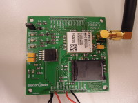
This project is a BoB (Break-out board) used to communicate (with a SIMcard) on the GSM network.The project works with the M95 module from Quectel :http://www.quectel.com/product/prodetail.aspx?id=7With this you can send SMS/MMS, receive SMS/MMS, manage call !Let me explain this project to you : Power supply
This project is a BoB (Break-out board) used to communicate (with a SIMcard) on the GSM network.
The project works with the M95 module from Quectel :
http://www.quectel.com/product/prodetail.aspx?id=7
With this you can send SMS/MMS, receive SMS/MMS, manage call !
Let me explain this project to you :
Power supply
There is a LDO regulator (MIC29302). The output of the regulator is 4.1V (recommended by the datasheet of the M95). You can input a voltage between 5v and 12v.
To power ON the module, you have to put the PWRKEY pin to VDD until 1/2second, the module will answer.
Connectors
There are 4 connectors on the PCB (K1, K2, K3, K4) if a user want to use this pins. The VCC pin is on K4.2 and the GND is on K4.1, K3.6 & K3.7. (you can find the pinout of the connector in the files attached)
To power on the module, you can add a push button or a signal from a microcontroller.
When you communicate with the module, you can just use RX and TX, or you can use too RTS, CTS to control. There is a resistor of 0 ohm on RTS. If you use just RX and TX you have to let this resistor. Otherwise if you use RX, TX, CTS, RTS you must remove this resistor.
LED
There are 2 differents LED :
- POWER : When there is power on the module, this LED will power on
- NETLIGHT : This led indicates the network. You can find the status with the datasheet page 52 (http://www.quectel.com/UploadImage/Downlad/M95_Hardware_Design_V1.3.pdf)
Here are the differents step to test the module :
- Power supply the module between 5v and 12v (the power LED should be on)
- Connect TTL-232R-5V cable from FTDI or our FT232R USB/Serial Bridge/BOB (http://www.elektor.com/ft232r-usb-serial-bridge-bob-110553-91) (put Rx FTDI on Tx module, and Tx FTDI and Rx module, don't forget the ground)
- Use a terminal (personnally I use "Docklight") to simulate a serial port.
Send the command AT (don't forget the Carriage Return (0x0D) or the module won't answer)
If the module says "OK", it means that everything is good !!
Steps to send an SMS (each time with the Carriage Return) :
- AT+CPIN=xxxx : to unlock you SIMcard, with xxxx your code)
- AT+CPIN? : Check if it's good, the module have to say "+CPIN: READY"
- AT+CMGF=1 : To put SMS message format in text mode
- AT+CSCS="GSM" : To put GSM as character set
- AT+CMGS"xxxxxxxxxx" : Put the telephone number of the person that you want to send a SMS
- You can now put text, and to send you have to finished by a CTRL+Z "0x1A"
You can find all AT commands on the datasheet :
http://www.quectel.com/UploadImage/Downlad/M95_AT_Commands_Manual_V1.2.pdf
ADD 05/08/2015 :
Steps to send an MMS (with the <CR>) :
- AT+QICSGP=1,"xxxxxx" : with xxxxxx your APN from your provider
- AT+QMMURL="xxxxxx" : with xxxxxx your MMSC
- AT+QMMPROXY=1,"xxx.xxx.xxx.xxx",zzzz : with xxx.xxx.xxx.xxx the IP adress of your proxy and zzzz the port (write some times xxx.xxx.xxx.xxx:zzzz) (you can find this informations on the website of your network)
- AT+QMMSW=0 : Clean MMS (to prepare configuration)
- AT+QMMSW=1,1,"yyyyyyyyyy" : with "yyyyyyyyyy" the telephone number to the person that you want to send MMS
- AT+QMMSCS="UTF8",1
- AT+QMMSW=4,1 : To put a title in your MMS (don't forget to finished by CTRL-Z)
- AT+QMMSEND=1 : To send your MMS. If everyting is ok, the module will answer you "+QMMNOTIFY: 1, 0, 0"
You can find all the commands in the PDF :
http://www.quectel.com/UploadImage/Downlad/GSM_MMS_AT_Commands_Manual_V1.1.pdf
With this commands you can send MMS with text. But you maybe want to add a picture ? So to add a picture and send it :
- You must have a terminal who allow sending picture (personnaly I used "RealTerm" (http://realterm.sourceforge.net/)
- before sending the picture, you have to say to the module that a picture will arrive with this command : AT+QFUPL="RAM:test.jpg",xxxxx : You will put into the RAM a fil named test.jpg with a size of xxxxx bytes
- You will have a message when the transfer is over
- Go to the previous steps to send MMS, and after step 7 you have to send this command : AT+QMMSW=5,1,"RAM:test.jpg"
Enjoy !!
Discussion (1 commentaire(s))