
In circuit capacitance meter part 2-modified with inclusion of inductivity
Measuring capcaitors from 1pF to 80mF and/or inductors from 1microH to 40H using a low voltage method that is robust against parasitic parallel or seriess resistance such that reliable measurements can be made withou removing the items from a circuit.
As part II of the previous Capmeter project
here a variant and extension of the in-circuit capacitance meter is presented.
The present version allows the measurement of cpacitors from 1pf to 80mF
AND inductors from 1uH to 40H.
The measured values are robust against parallel (for C) or seies (for L) resistance
over a wide range. Additional indicative information on C series resistnce is provided.
Voltages applied to Cx are confined between +-200mV and the maximum effective voltage
across Lx would be 10mV. Thus most semiconductor elements connected to them within a circuit
would still not conduct. Parallel resistors to Cx or (series) resistivity of Lx are
simulatneously measured and do not influence the measured capacitance or inductance
as long as overrange ssituations can be avoided.
The version 2 setup can be considered as an autonomous separate analog part that
yields Cx, Lx and Rparallel .. values in terms of DC-voltages.
The second part consist of a MIcroocontroller (Arduino) with a (4 channel) ADC.
In my realisation the ADS1115 (4 channel, 16bit) is used in order to supply
good resolution. Still a simplification using A2-A4 analog Arduino inputs should work
(with somewhat less accuracy/resolution).
Range switching is done manual, which gave better control on the measurements and
explorations.
The Microcontroller is ssupplied with the analog output voltages together with
voltages the encode the setting of the range switches. Using all of these inputs it
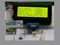
computes the Cx, Lx and Rp, Rs values and supplies the in an 20x4 lcd display.
The basic principle of the measurement has alrready been describe in the description
of the first version. But a very short of the essentials is reiterated here:
Starting with a triangular drive voltage U(t) with a given slope we:
a.) apply the (attenuated) U(t) to a test capacitor and measure the resulting current Ic(t)
b.) use a resistor R to convert the drive voltage U(t) to a drive current I(t) through an inductor Lx and measure the voltage Ul across the inductor, the maximum Ul of 10mV is small enough to not
significangtly change the drive current (using U=+-2.5V).
Effective sampling of the signal voltage (R_shunt*Ic) or (Ul) allows to eliminate the effect of
parallel respectively series resistances. Difference to off-center samploing windows
yields information on the latter resistances.
Using "zero-offset" high bandwidth op-amps (OPA2182) allows to work with current measuring shunt
voltages inte range of 1mV. But the small residual effect of the shunt voltage is further reduced (compensated)
by a (positive) feedback of this voltatge to the excitation U(t). In particular this helps to
compensate to the shunt contribution to Rs.
Detailed comments on the sschematics and e:xamples on real world measurements are in the detailed description.
here a variant and extension of the in-circuit capacitance meter is presented.
The present version allows the measurement of cpacitors from 1pf to 80mF
AND inductors from 1uH to 40H.
The measured values are robust against parallel (for C) or seies (for L) resistance
over a wide range. Additional indicative information on C series resistnce is provided.
Voltages applied to Cx are confined between +-200mV and the maximum effective voltage
across Lx would be 10mV. Thus most semiconductor elements connected to them within a circuit
would still not conduct. Parallel resistors to Cx or (series) resistivity of Lx are
simulatneously measured and do not influence the measured capacitance or inductance
as long as overrange ssituations can be avoided.
The version 2 setup can be considered as an autonomous separate analog part that
yields Cx, Lx and Rparallel .. values in terms of DC-voltages.
The second part consist of a MIcroocontroller (Arduino) with a (4 channel) ADC.
In my realisation the ADS1115 (4 channel, 16bit) is used in order to supply
good resolution. Still a simplification using A2-A4 analog Arduino inputs should work
(with somewhat less accuracy/resolution).
Range switching is done manual, which gave better control on the measurements and
explorations.
The Microcontroller is ssupplied with the analog output voltages together with
voltages the encode the setting of the range switches. Using all of these inputs it
computes the Cx, Lx and Rp, Rs values and supplies the in an 20x4 lcd display.
The basic principle of the measurement has alrready been describe in the description
of the first version. But a very short of the essentials is reiterated here:
Starting with a triangular drive voltage U(t) with a given slope we:
a.) apply the (attenuated) U(t) to a test capacitor and measure the resulting current Ic(t)
b.) use a resistor R to convert the drive voltage U(t) to a drive current I(t) through an inductor Lx and measure the voltage Ul across the inductor, the maximum Ul of 10mV is small enough to not
significangtly change the drive current (using U=+-2.5V).
Effective sampling of the signal voltage (R_shunt*Ic) or (Ul) allows to eliminate the effect of
parallel respectively series resistances. Difference to off-center samploing windows
yields information on the latter resistances.
Using "zero-offset" high bandwidth op-amps (OPA2182) allows to work with current measuring shunt
voltages inte range of 1mV. But the small residual effect of the shunt voltage is further reduced (compensated)
by a (positive) feedback of this voltatge to the excitation U(t). In particular this helps to
compensate to the shunt contribution to Rs.
Detailed comments on the sschematics and e:xamples on real world measurements are in the detailed description.
Want to build a project?
Bring your design to life with the Elektor PCB Service, powered by Eurocircuits. Upload the project files and order professionally manufactured PCBs or assembled boards through a proven European production platform.
Supporting KiCad, Eagle, Gerber, and ODB++ formats, the service is suitable for everything from prototypes and validation builds to series production and volume manufacturing.
Made in Europe. Fast. Reliable. Professional.
Mises à jour de l'auteur