
Irrigation Controller
Let's face it: I'm a poor gardener. This project shall help me watering and monitoring the plants on my balcony.
Introduction
Let's face it: I'm a poor gardener. My main problem: Forgetting to water the plants. I'm thinking about this problem for many years now. Many ideas came to my mind, but I didn't actually start something in this regard.
In 2017, sometime between spring and summer, I stumbled across the Gardena MicroDrip system. It's a starter-kit that uses a (indeed very very small) pump within some sort of water reservoir. The last part was pretty important, because my balcony has no direct water tap. The kit came with some pipe, some drippers, the water pump and a very basic controller. The controller is able to do some fixed-interval programs, but you can't freely program it.
I'm aiming at more flexibility in regard to watering the plants. The basic idea is still to use fixed intervals, but drop waterings in case of rain or extend the watering time if the sun was shining heavily.
Goals
In the first step, I'm going to implement just the fixed interval watering. That's more or less what the simple Gardena controller can do, but with the addition of monitoring the water reservoir. This will allow me to receive alarms, when the water level is too low. Additionally, the pump won't run dry anymore as it does with the Gardena controller. This is what I expect to be completed within the competitions' runtime.
At a later stage - after the competition, the second step will be adding more advanced logic to make the watering more flexible. The basic idea will be to still to use fixed intervals, but drop waterings in case of rain or extend the watering time if the sun was shining heavily. I'm planning to address this step much later this year.
Hardware platform
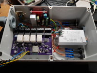
My hardware platform is based on an ESP32. I designed a base board with some relays, power supply, UART interfaces (for sensors, e.g. the fill level sensor for the reservoir) and the ESP-WROOM-32 module.
On the top edge of the board are connectors for power, the relay outputs and the UARTs. The connectors are screw terminals which can be disconnected without loosening the screws, which might be handy when installing the hardware in its IP67 enclosure.
The design has two switching regulators: The first one is the main regulator for the 3.3V I use to power the ESP32 and all other digital stuff on the board. The second regulator is used to power the relays and external sensors. This regulator is normally off and can be activated via a GPIO of the ESP32. The UART level-shifters are also held in standby by default and can be powered up by the ESP32 on demand. I did this to reduce the power consumption as much as possible. I plan on driving the whole system on solar power sometime in the future. That's also the reason why I connected an ADC channel to the power input for voltage monitoring.
The fill level sensor (which is another project on its own) will be connected to one of the UARTs. Measurements will be triggered via a simple command/response scheme. I decided to decouple the two projects to try out different approaches for measuring the fill level in the real world. With the use of a generic command interface it doesn't matter how the level is actually measured.
Project resources
The software source code is published on Github where I will also publish up-to-date documentation: https://github.com/mwick83/irrigation_ctrl
The hardware will also be published on Github: https://github.com/mwick83/irrigation_ctrl_hw
I also blog about the project on my website under the hashtag #IoP - Internet of Plants.
Let's face it: I'm a poor gardener. My main problem: Forgetting to water the plants. I'm thinking about this problem for many years now. Many ideas came to my mind, but I didn't actually start something in this regard.
In 2017, sometime between spring and summer, I stumbled across the Gardena MicroDrip system. It's a starter-kit that uses a (indeed very very small) pump within some sort of water reservoir. The last part was pretty important, because my balcony has no direct water tap. The kit came with some pipe, some drippers, the water pump and a very basic controller. The controller is able to do some fixed-interval programs, but you can't freely program it.
I'm aiming at more flexibility in regard to watering the plants. The basic idea is still to use fixed intervals, but drop waterings in case of rain or extend the watering time if the sun was shining heavily.
Goals
In the first step, I'm going to implement just the fixed interval watering. That's more or less what the simple Gardena controller can do, but with the addition of monitoring the water reservoir. This will allow me to receive alarms, when the water level is too low. Additionally, the pump won't run dry anymore as it does with the Gardena controller. This is what I expect to be completed within the competitions' runtime.
At a later stage - after the competition, the second step will be adding more advanced logic to make the watering more flexible. The basic idea will be to still to use fixed intervals, but drop waterings in case of rain or extend the watering time if the sun was shining heavily. I'm planning to address this step much later this year.
Hardware platform
My hardware platform is based on an ESP32. I designed a base board with some relays, power supply, UART interfaces (for sensors, e.g. the fill level sensor for the reservoir) and the ESP-WROOM-32 module.
On the top edge of the board are connectors for power, the relay outputs and the UARTs. The connectors are screw terminals which can be disconnected without loosening the screws, which might be handy when installing the hardware in its IP67 enclosure.
The design has two switching regulators: The first one is the main regulator for the 3.3V I use to power the ESP32 and all other digital stuff on the board. The second regulator is used to power the relays and external sensors. This regulator is normally off and can be activated via a GPIO of the ESP32. The UART level-shifters are also held in standby by default and can be powered up by the ESP32 on demand. I did this to reduce the power consumption as much as possible. I plan on driving the whole system on solar power sometime in the future. That's also the reason why I connected an ADC channel to the power input for voltage monitoring.
The fill level sensor (which is another project on its own) will be connected to one of the UARTs. Measurements will be triggered via a simple command/response scheme. I decided to decouple the two projects to try out different approaches for measuring the fill level in the real world. With the use of a generic command interface it doesn't matter how the level is actually measured.
Project resources
The software source code is published on Github where I will also publish up-to-date documentation: https://github.com/mwick83/irrigation_ctrl
The hardware will also be published on Github: https://github.com/mwick83/irrigation_ctrl_hw
I also blog about the project on my website under the hashtag #IoP - Internet of Plants.
Mises à jour de l'auteur