
Mechanical LED fader
I wanted to end my diarrhea of LED fader designs with a humoristic design. Though it looks like a bad joke, it still has a nice LED fade effect.
I think humor makes life easier.
So i could not resist to design a mechanical LED fader.
Though it might seem like a bad joke, the circuit actually works very well, in terms of generating a nice LED fade effect. In terms of mechanical noises and life expectancy, the score is probably not so good.
In some amplifiers (even nowadays) you find servo-potmeters to control the volume of the amplifier with a remote-control. The servo-potmeter consists of a potmeter (mostly logarithmic in audio applications) and a motor that is connected to the potmeter shaft via gears and a slip clutch. A nice combination of analog and digital techniques.
This concept was the nutritional basis of this LED fader circuit idea.
I wanted to use a stereo logarithmic potmeter that is moved back and forth by a slow moving geared DC motor. That way i could generate an exponential changing current to make the LED brightness appear to fade linearly to the human eye.
One of the potmeters would be used to feedback the position of the wiper and the other potmeter to generate the exponential current for the LED.
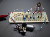
For the first experiment, i used a mono linear potmeter, because it is possible to use one potmeter both for position feedback and for the LED, and a small geared DC motor. Both were hot glued onto a piece of copper clad board and the axis of the potmeter hot-glued to the axis of the motor. It is possible to adapt a linear potmeter so it becomes semi-logarithmic, by placing a parallel resistance over one half of the potmeter.
See : http://www.learnabout-electronics.org/Resistors/resistors_09a.php
But you can use a logarithmic potmeter as well and place a resistance parallel to tweak the voltage curve so the LED fades nicely. The resistance ratio of the potmeter and this parallel resistance determines the slope of the logarithmic curve.
A comparator with a large hysteresis, provided by a strong positive feedback, compares the voltage of the potmeter wiper ( = position of the motor) with a reference voltage. Because of the positive feedback, the output of the comparator will pull the reference voltage up or down. So, depending on the state of the comparator, the reference voltage has 2 levels: a high and a low one. This means that the comparator will react to 2 different wiper positions. Because the potmeter wiper is connected to the inverting input of the comparator, the output of the comparator will swing low when the voltage on the wiper (= position of the motor) becomes higher than the high reference voltage. When the wiper voltage becomes lower than the low reference
voltage, the comparator output will swing high again.The comparator output controls a double pole/double throw 12V DC relay via a BC547 transistor.
The relay functions as a mechanical H-bridge, that makes the motor run clockwise when the comparator output is high, or counter-clockwise when the output is low.
By connecting the motor to the potmeter axis and choosing the right polarities for the motor and potmeter, we have a closed loop system that toggles (oscillates) between 2 states, like an ON/OFF control system.
The result of closing the loop, is that the motor will move the potmeter back and forth continuously between the 2 positions on the wiper, where the wiper voltage exceeds the comparator reference voltage.
At each of the 2 positions, the motor direction is reversed by the relay, that is controlled by the comparator output.
A resistor is placed parallel to the bottom part of the potmeter. The result is that the linear potmeter generates a semi-logarithmic voltage on the wiper.
This wiper voltage is not only used as a position feedback, but also to control the LED. The wiper voltage is converted to a current using a transistor. The transistor base is connected to the wiper via a diode, that is used to eat away 0.6V from the wiper voltage. This is because the wiper can not move all the way to 0 volts, due to the fact that the comparator output does not reach 0V and the positive feedback can not pull the reference voltage all the way to 0V.
To be able to adjust the speed of the motor, i added an adjustable zener diode, formed by a BC337 transistor and a 10K trimpot meter to supply power to the motor. The motor that i used only draws about 70mA at 12V, so 0.6W.
To adjust the reference voltage for the comparator, a 10K trimpot meter is used. By adjusting the trim potmeter, the 2 threshold voltages for the comparator are shifted up or down. This shifts the area on the potmeter over which the motor moves back and forth, but it also shifts the voltage that is used for the LED. So this adjustment is used to make the LED just go off when the potmeter is at the "lowest" position.
The curve for the LED fading can be tweaked by changing R8, that is put parallel with the bottom half of the potmeter.
So i could not resist to design a mechanical LED fader.
Though it might seem like a bad joke, the circuit actually works very well, in terms of generating a nice LED fade effect. In terms of mechanical noises and life expectancy, the score is probably not so good.
In some amplifiers (even nowadays) you find servo-potmeters to control the volume of the amplifier with a remote-control. The servo-potmeter consists of a potmeter (mostly logarithmic in audio applications) and a motor that is connected to the potmeter shaft via gears and a slip clutch. A nice combination of analog and digital techniques.
This concept was the nutritional basis of this LED fader circuit idea.
I wanted to use a stereo logarithmic potmeter that is moved back and forth by a slow moving geared DC motor. That way i could generate an exponential changing current to make the LED brightness appear to fade linearly to the human eye.
One of the potmeters would be used to feedback the position of the wiper and the other potmeter to generate the exponential current for the LED.
For the first experiment, i used a mono linear potmeter, because it is possible to use one potmeter both for position feedback and for the LED, and a small geared DC motor. Both were hot glued onto a piece of copper clad board and the axis of the potmeter hot-glued to the axis of the motor. It is possible to adapt a linear potmeter so it becomes semi-logarithmic, by placing a parallel resistance over one half of the potmeter.
See : http://www.learnabout-electronics.org/Resistors/resistors_09a.php
But you can use a logarithmic potmeter as well and place a resistance parallel to tweak the voltage curve so the LED fades nicely. The resistance ratio of the potmeter and this parallel resistance determines the slope of the logarithmic curve.
A comparator with a large hysteresis, provided by a strong positive feedback, compares the voltage of the potmeter wiper ( = position of the motor) with a reference voltage. Because of the positive feedback, the output of the comparator will pull the reference voltage up or down. So, depending on the state of the comparator, the reference voltage has 2 levels: a high and a low one. This means that the comparator will react to 2 different wiper positions. Because the potmeter wiper is connected to the inverting input of the comparator, the output of the comparator will swing low when the voltage on the wiper (= position of the motor) becomes higher than the high reference voltage. When the wiper voltage becomes lower than the low reference
voltage, the comparator output will swing high again.The comparator output controls a double pole/double throw 12V DC relay via a BC547 transistor.
The relay functions as a mechanical H-bridge, that makes the motor run clockwise when the comparator output is high, or counter-clockwise when the output is low.
By connecting the motor to the potmeter axis and choosing the right polarities for the motor and potmeter, we have a closed loop system that toggles (oscillates) between 2 states, like an ON/OFF control system.
The result of closing the loop, is that the motor will move the potmeter back and forth continuously between the 2 positions on the wiper, where the wiper voltage exceeds the comparator reference voltage.
At each of the 2 positions, the motor direction is reversed by the relay, that is controlled by the comparator output.
A resistor is placed parallel to the bottom part of the potmeter. The result is that the linear potmeter generates a semi-logarithmic voltage on the wiper.
This wiper voltage is not only used as a position feedback, but also to control the LED. The wiper voltage is converted to a current using a transistor. The transistor base is connected to the wiper via a diode, that is used to eat away 0.6V from the wiper voltage. This is because the wiper can not move all the way to 0 volts, due to the fact that the comparator output does not reach 0V and the positive feedback can not pull the reference voltage all the way to 0V.
To be able to adjust the speed of the motor, i added an adjustable zener diode, formed by a BC337 transistor and a 10K trimpot meter to supply power to the motor. The motor that i used only draws about 70mA at 12V, so 0.6W.
To adjust the reference voltage for the comparator, a 10K trimpot meter is used. By adjusting the trim potmeter, the 2 threshold voltages for the comparator are shifted up or down. This shifts the area on the potmeter over which the motor moves back and forth, but it also shifts the voltage that is used for the LED. So this adjustment is used to make the LED just go off when the potmeter is at the "lowest" position.
The curve for the LED fading can be tweaked by changing R8, that is put parallel with the bottom half of the potmeter.
Discussion (1 commentaire(s))