
mini-NTP server with GPS
This is a mini-NTP based on a ESP32. Time will be provided from the GPS receiver and a DS3231 if no GPS-signal is avaliable, to server time to your networkcleints.
Firmware update to V1.4 now ready
.With the feedback and help from our readers some mayor bugs have been removed, now the sync with linux and windows machines workes as desired. Also a small problem within the WebUi and iPhones has addessed. For those thta use an GPS module that suffers from the weekrollover bug and won't get a new firmware, now you can adjust for this in the webinterface. This will expand the usablility of the module and also hopfully reduce e-wast. For a bit more easy of use you can now change / swap the displaycontent during runtime with the boot button. Sometimes small patches take a bit longer. With the Firmware 1.1 the NTP-Sever finally gained support for static IPv4 address settings. This meant a few changes in the code for the ESP32 and getting the HTML page with the requiered javascript ready. As the basic setup has only one display you can now switch between both if you press during runtime the bootbutton. Now you can choose the information you like to have without accessing the webserver on the ESP32. Still we need to inverstigate why the Raspberry Pi is not taking the time from the NTP-Server. But after the update back to the reason why we buidl it in the first place.
This mini-NTP sever has been buid a while ago. The first prototype was build for a exibition in france, 2018. Based on a ESP8266, a DS3231 based RTC and a small 0,96" OLED. This allowed the exhibits to get the time from a NTP on locations where the internetconnection is sometimes not given. This prototype since then as traveld to some exibitions ,like the electronica 2018 in munich. Also this mini-NTP served as timesever in the lab for some of your clocks and raspberry pi. Also this comes handy as we can manipulate time on the NTP server an test some condercases on some systems on the lab. Also if you have a small fleet of raspberry pi in your netwok this can be used to synchronize the time on the pis without connection to the internet. But the NTP had one major drawback, the DS3231 RTC used in this build was from a questinable source and the chip more a lookalike than a real DS3231. As a result the clock had an accuracy problem, meaning that it was after a month four to five minutes ahead of time.
This requiered every month a manual adjust to the clock. As this is not a problem for a exibitions where you set the clock and for a week are good to go, in the lab this leaded to some unhappy faces as the clocks synchronized to this NTP suggested that you just have missed an appointment or won't catch the bus. This was the point were the prototype requested a complete overhaul.
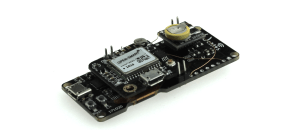
The ESP8266 was swapped with a ESP32 and a GPS receiver was added to synchronize time. As the choosen module comes with a onboard OLED we don't need a seperate display. For the GPS receiver we used one form our shop, which also exposes the point per second signal to a pin. For the RTC we used a DS3231 module we found in the lab, originally designed to be used on a raspberry pi.
Ingredients
We need a few modules to get all together:
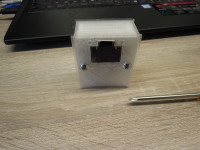
Basically we use an ESP32 as core, a SSD1307 based I²C OLED, a GPS receiver and a RTC. This are modules sutable for a fast homebuild. But sometimes you like to get it even a bit smaller and may reduce modules. In this case we used a ESP32 Module with combined OLED and a DS3231 based RTC you can usually find on raspberry pis. This all is gone into a small housing and the components attached in a sandwich way with a bit of copper wire.
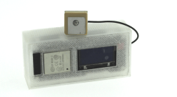
This makes it posible to put it in a small 3d printed enclosure and put it to a sutable location.
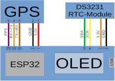
For the connection, the I²C is not on the usual pins for the ESP32, for the used module this is here on GPIO4, SCL, and GPIO5, SDA. We need to know this because we also need to attatch the DS3231 also to the I²C-Bus. For the GPS module we have choosen to use GPIO13 as RX-pin and GPIO15 as TX-pin. The connection need to be crossed, this means TX-pin to RX-pin. For the power supply the module needs 5V VCC we can get directly from the module.
After the basic hardwaresetup we also need a bit of software. We used https://github.com/liebman/ESPNTPServer to see which problems may arise in the build. For the software we repurposed some older labs projects like the pinball clock. Basically we used the timekeeping corefunctions from the pinball clock and it's ability to synchronize to different sources with different priorities. After the startup the DS3231, or also supported, the DS1307, will provide the time untill the GPS has revieived this information. If no clock is found the Server will run without the time from the i²C Clock and start counting form 1.1.1970 untill the first time from the GPS arrive. This means simply if you don't have a I²C Clock the ESP32 runs anyway, this is also true for the GPS part. If there is no GPS receiver connected, the ESP32 will simpily run form the DS3231 or use its internal timers.
NTP-Server
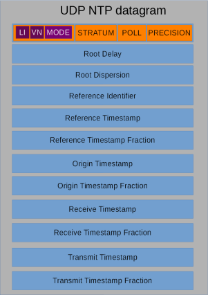 For the NTP there is UDP ( User Datagram Protocol ) used for information exchange. The NTP simply listens to Port 123 for incomming NTP-request and sends a packet with the added data back. If we look at the datagram we need to fill in a few items. LI, VN and MODE are Bitfilds, where LI indicates that we have a leap second at the end of the minute. VN gives us the protocol version used and MODE shows the mode of the system, here server.
The Root Delay gives the distance between this server and the next server. As we are the only one in the chain we set the field to 1. This is also the same for the Root Displersion. As Refference Identifier we use "PPS" to show that we run on a pulse per second base.
We fill the Reference Timstamp with the current time and also set the Received and Transmit Timestamp accordingly. As the ESP32 only counts seconds we can't fill the factional part with any usefull infromation, so we set this to zero. This also means that we need to set the PRECISION field with a given valule. This is log2( Clock Jitter ) means at least one second we have form the missing fraction plus the jitter intoduced by calling your functon sto get the time. This is not 100% perfect but will do the job.
Timesources
As seen in the introduction we have two timesources. One it the DS3231, out RTC, and the other is the GPS wit a puls per second signal. As we have varing reception conditions this signal can somtime be present somtimes not. The signal is hooked to an interrupt and will be used as soon as it is avalible, meaning a switch over from the internal second counting to the external one. At the same point we monitor the signal. If the pulse is missing more than 1400ms we assume a lost of reception and fall back to the internal time source. Also this means we need to count a second and do it again in 600ms, as we are 400ms over the expected pulse.Also we get from the GPS-reveiver timestamps. It is sufficent to process and synchronize every 10 minutes to this timstamp to keep the NTP on time, as we are usually have the pulse per second signal from the gps.
Besides keeping time we can also disable the sync to the gps and only use the pusle per second to test systems in our networkt, how they behave on special ocasions, like switching from summer to wintertime.
Get and Compile the Software
The software is attached on this article. Also you may check back for new releases on this page. But if you like you can also grab a copy from Github. Here you may also find new preview versions or some mods to the original one.You need to install the Arduino IDE and the ESP32 board pakage. Also you need to install some librarys to get the code compiled. These are basically:
- U8G2
- Time
- Ticker
- TinyGPS++
- RTCLib
- ArduinoJson 6.x
- CRC32
ESP32 Setup
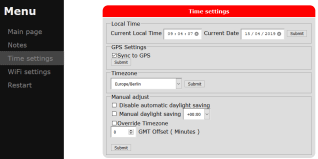
The setup of the ESP32 is quite simple. After you build the system it will power up as accesspoint. Form there you can connect to it and set your wifi. Also you can set all time relevant settings form the webinterface.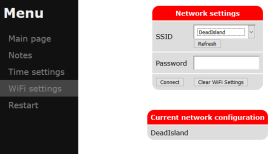
Afterwards the ESP32 will try to connect to your wifi and to obtain an ip. If this is done you can go the the webinterface and may do further adjustments.Also you can swap the two displays, or if olny one is connected you can choos what to show.

This is basically all you need to do. The NTP will now respind to requests from your local network.
Parts that can be used for the build
If you like to order the parts from the elektorshop we provide here some linke to the modules that can be used for the build:1 x OPEN SMART GPS
1 x Wemos Lolin ESP32 OLED
For the RTC you can choose a DS3231 based or if you like you
can also use a DS1307 based one as been found here:
1 x Adalogger FeatherWing - RTC + SD Add-on
OPTIONAL:
1x 0,96" I²C OLED
Build This Project
Bring this design to life with the Elektor PCB Service, powered by Eurocircuits. Upload the project files and order professionally manufactured PCBs or assembled boards through a proven European production platform.
Supporting KiCad, Eagle, Gerber, and ODB++ formats, the service is suitable for everything from prototypes and validation builds to series production and volume manufacturing.
Made in Europe. Fast. Reliable. Professional.
Discussion (29 commentaire(s))