
Platino Serial Bus Tester [130409]
An Elektor Platino-based system intended as a debugging tool for serial communication busses.
A word about vocabulary
Let’s start by defining some context. A ‘bus’ is a group of signals. A ‘communication protocol’ is a set of rules that dictates how data is transmitted between computers. A ‘standard’ is a thing or idea against which something similar can be measured or compared. ‘Serial’ means one bit at a time. ‘Synchronous’ serial signals comprise separate data and clock signals; ‘asynchronous’ serial signals only have data signals.In this article we will use the term ‘protocol’ for the way bits are supposed to be ordered on the line (e.g. one start bit, eight data bits, no parity, and one stop bit). ’Standard’ will refer to the physical expression of the data (e.g. the voltage levels and signal polarities on the line).
Specifications
With the above vocabulary in mind we can write down the following list of specifications for our test tool:- Multi-protocol
- Multi-standard
Because this list is rather short whereas our project is an excellent target for feature creep, let’s add some more detail.
Multi-protocol (one at a time):
- Plain vanilla serial
- I2C / SMBus
- SPI
- Other? 1-Wire?
Multi-standard:
- RS-232
- RS-485 / DMX512
- MIDI
- 5 V
- 3.3 V
With these standards we cover a pretty large range of possible protocols. The popular protocols are present from the start, while more exotic ones can be added later on.
From an operational perspective we specify flexibility.
Multi-standard hardware
As mentioned above, as the basis for our project we chose the Elektor Platino platform fitted with a backlit alphanumerical display with four 20-character lines, a rotary encoder, a pushbutton, a buzzer, and a tricolour LED. Equipped with an ATmega1284P microcontroller it has ample memory (128 KB program memory plus 16 KB of RAM) for serial protocols and nifty features. To that we added an extension board with the required interfaces for our serial standards.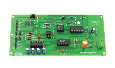
If we load a suitable bootloader into the MCU the whole system becomes Arduino compatible and we can profit from the large number of Arduino libraries available online.
Multi-protocol software
Because our space is limited we will not waste it on such futile details as hardware descriptions.Click here to learn everything about the Elektor Platino board.
Even though the ATmega1284P has hardware peripherals for the main serial protocols “UART”, I2C and SPI, its fixed pinout makes that we cannot profit from all of them together with Platino’s user interface elements. For this reason we decided to handle the relatively low-speed I2C protocol (400 kHz max.) in software (bit-banged master up to 400 kHz, bit-banged slave up to 10 kHz), giving the SPI bus the opportunity to fully express itself up to 8 MHz. This also implies that only one of the two hardware UARTs is available, as PD2 (RXD1) and PD3 (TXD1) are needed to control part of the LCD instead of the SPI lines PB6 (MISO) and PB7 (SCK). For TTL-level serial data a software UART is required using some of the pins of the SPI bus.
In case it wasn’t clear already, our tester will do only one serial protocol at a time.
Ergonomics come first
Because the tester’s usefulness depends for a large part on its ergonomics, we have spent quite some time on fine-tuning the user interface (UI). The objective was to make using the device as easy and comfortable as possible even though the display has limited space and cannot do colourful graphics. All the parameters are accessible by rotating and pushing the rotary encoder, and without going through many layers of menu. The result is, paradoxically, a rather cryptic main screen, but, as any user will quickly discover, easy to master.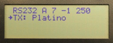
Spinning the encoder will move the little arrow to the next parameter; pushing the encoder will change the parameter’s value or enter edit mode for parameters with a wide range (serial baud rate for instance).
Main screen
- Protocol - placing the cursor (the arrow) at the left of the protocol name by rotating the encoder and then pressing its pushbutton will bring up the protocol’s submenu where you can set the parameters specific to the protocol.
- Data display format - press the encoder to toggle between ASCII ('A') or hexadecimal ('H').
- TX data size - press the encoder’s pushbutton to enter edit mode. Rotating the encoder will increment or decrement the field’s value (0…7, yes it is possible to send nothing). Press the rotary encoder again when done. For most protocols this value will be set to the selected protocol mode (e.g. 3 for MIDI) but this can be overridden here, allowing to send more or less data.
- Repeat count - press the encoder’s pushbutton to enter edit mode. Rotating the encoder will increment or decrement the field’s value (-1…99, -1 means forever). Press the rotary encoder again when done.
- Repetition rate - press the encoder’s pushbutton to enter edit mode. Because this field can have up to four digits (‘0000’ to ‘9999’ milliseconds), rotating the encoder will increment or decrement the first digit. Pressing the rotary encoder again will move the cursor to the next digit.
- TX data - press the encoder’s pushbutton to enter string editing. It can work in ASCII as well as in hexadecimal mode, depending on the data display format field.
Note that TX data can be up to seven bytes long. This upper limit is imposed by the available space on the second line. When the data display format is hexadecimal there is just enough space to print seven hexadecimal values.
The third and fourth lines are reserved for RX data.
Protocol menus
RS-232 & RS-485
RS-232 and RS-485 share the port settings, but the output is routed to different interfaces. (RS-485 also uses a bus enable signal.)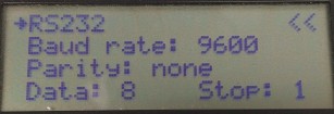
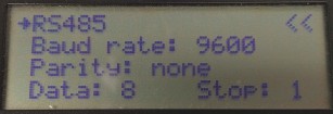
Baud rate: 1 Hz - 2 MHz
Parity: none, odd, even
Data (bits): 5-8
Stop (bits): 1 or 2
SPI
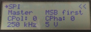
Role: Master (SPI) or Slave (spi)
Data direction: MSB or LSB first
Mode (CPOL & CPHA): 0-3
Speed: 125 kHz, 250 kHz, 500 kHz, 1 MHz, 2 MHz, 4 MHz, 8 MHz
Signal level: 5V or 3V3
I2C & SMBUS
The SMBUS protocol uses most of the settings from the I2C menu, except for slave mode as our SMBUS implementation only supports master mode.I2C mode does start-stop-start (S-P-S) between write and read, SMBUS does a repeated start (Sr) between write and read.
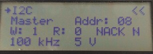
Role: Master (I2C) or Slave (i2c)
Address (slave or mine when I am slave): 0-0x7f
W(rite count): 0-7 bytes (also used for SMBUS block protocols)
R(ead count): 0-99 bytes (also used for SMBUS block protocols)
(ignore) NACK: Y(es) or N(o) (ignoring NACK will make the master do the full transaction even when there is no slave responding or even present)
Speed (master): 10, 25, 50, 100, 200, 400 kHz. In slave mode only clock speeds up to 10 kHz are supported.
Signal level: 5V or 3V3
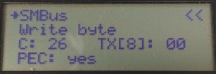
Protocol: quick command, send byte, receive byte, write byte/word/32/64/block, read byte/word/32/64/block, process call, block write-read
C(ommand): 0-0xff
TX[8] (8th databyte for write64 protocol): 0-0xff
PEC: yes or no
MIDI
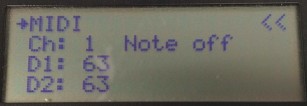
Ch(annel): 1-16
Status: Note off, note on, aftertouch, control change, program change, channel pressure, pitch bend, system exclusive
D1 (first data byte): 0-127
D2 (second data byte): 0-127
Hardware requirements
- Platino (150555-1), fully assembled with 16 MHz crystal & ATmega1284P. Rotary encoder on S5 and pushbutton on S4 (A for left-handed, C for right-handed). RGB LED: don’t connect blue (the pin closest to the centre of the board) as this pin is also used for the LCD backlight.
- Serial Bus add-on board 130409-1.
- Arduino IDE (tested with 1.8.0) with latest Platino boards package from Elektor GitHub.
- Arduino bootloader for ATmega1284P included in Platino boards package (optiboot_platino1284p.hex, fuses low=0xff, high=0xde, extended=0xfd).
- Attached firmware.
Click here to learn everything about the Elektor Platino board.
Platino solder jumpers
Jumper |
Position | Function |
| JP1 | C | Buzzer on PC4 |
| JP2 | - | does not exist |
| JP3 | C | LCD backlight on PC5 |
| JP4 | B | Rotary encoder A on PB0 |
| JP5 | B | Rotary encoder B on PB1 |
| JP6 | B | Rotary encoder pushbutton on PB2 |
| JP7 | B | Pushbutton on PB3 |
| JP8 | DIP40 | Allow PC6 |
| JP9 | PB7 | Allow PB7 |
| JP10 | PB6 | Allow PB6 |
| JP11 | DIP40 | ISP SCK on PB7 |
| JP12 | DIP40 | ISP MISO on PB6 |
| JP13 | DIP40 | ISP MOSI on PB5 |
| JP14 | C | LED1 blue on PC7 |
| JP15 | D | LCD RS on PD2 |
| JP16 | D | LCD E on PD3 |
Build This Project
Bring this design to life with the Elektor PCB Service, powered by Eurocircuits. Upload the project files and order professionally manufactured PCBs or assembled boards through a proven European production platform.
Supporting KiCad, Eagle, Gerber, and ODB++ formats, the service is suitable for everything from prototypes and validation builds to series production and volume manufacturing.
Made in Europe. Fast. Reliable. Professional.
Discussion (1 commentaire(s))