
Quasi analog exposure timer for the dark room
Outperforms simple analog timers and still has simple design and operation
A basic analog timer has a potentiometer to set the required time, eventually a range switch and a start button.
A digital timer is normaly operated by a keyboard or rotary encoder and a display and is therefore operated in a completely different way.
This digital timer is operated in an analog way, but has a lot better accuracy and stability.
A potentiometer is used to set the time required and with the range switch one can select from 3 ranges: [1 to 10], [2.5 to 25] and [10 to 100] seconds. Other ranges can be simply defined in the program.
According to the datasheet of the microcontroller used, accuracy of the timing is +/- 1 % using the internal oscillator. No crystal is used.
The scaling of the time is completely linear and depends only on the quality of the potentiometer, which only serves as voltage divider. Therefore the calibration of the potentiometer scale can be done with an accurate universal meter.
The range is selected by a 3-position (ON-OFF-ON) switch, connected to a second analog input; 0V=1, 2.5V=2, 5V=3. The multiplication factors for the ranges are exact, so no separate calibration is needed for each scale.
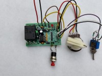
For the first test I (mis)used Elektor PCB 140574-1 (see photo). The final version is realized on veroboard. Because the circuit is very simple no PCB was designed for it.
The software is written in C for the CC5X compiler of B.Knudsen. The free version can be used for this small program.
At the start of the timing interval the A/D convertor samples the potentiometer. This value is multiplied with a scaling factor and added to an offset. The result is put into the comparator for timer1, which generates an interrupt at a frequency between 2 and 20 Hz.
Often an interrupt routine is called by the timer1 comparator but the code in this program is very simple and fast enough because only the decrement of a range dependant variable and a zero-check is done. Therefore the interrupt flag is polled in the main loop. If the decremented variable becomes zero the output is switched off and the microcontroller is put into sleep.
Change of the settings of the potentiometer or the switch during a running interval has no impact on the timing. The only way to stop a running timer is by pressing the reset button (or by removing the power).
If the timer is active, ouput RA5 is toggled (0.5 to 5 Hz) to show activity; eventually a LED with 1k series resistor can be connected to this output.
If other ranges are required, the multiplication factors MULT1, MULT2 and MULT3 can be changed. Max. is over 9 hours; if a longer time is needed the variable rtim must be changed from 16 to 24 bits (uns24 instead of uns16); this is not tested by me, because of limited testing time and not available in the free version of the compiler.
If more different ranges are needed, switch S1 can be replaced by a multi-position switch and more (equal) resistors are needed. In the program the lines after GetAD(1) must be changed accordingly and more MULTx factors must be added.
If you prefer the ranges to start at 0 instead of at 10% of the max. value the comment in the program shows you which constants you must change.
A digital timer is normaly operated by a keyboard or rotary encoder and a display and is therefore operated in a completely different way.
This digital timer is operated in an analog way, but has a lot better accuracy and stability.
A potentiometer is used to set the time required and with the range switch one can select from 3 ranges: [1 to 10], [2.5 to 25] and [10 to 100] seconds. Other ranges can be simply defined in the program.
According to the datasheet of the microcontroller used, accuracy of the timing is +/- 1 % using the internal oscillator. No crystal is used.
The scaling of the time is completely linear and depends only on the quality of the potentiometer, which only serves as voltage divider. Therefore the calibration of the potentiometer scale can be done with an accurate universal meter.
The range is selected by a 3-position (ON-OFF-ON) switch, connected to a second analog input; 0V=1, 2.5V=2, 5V=3. The multiplication factors for the ranges are exact, so no separate calibration is needed for each scale.
For the first test I (mis)used Elektor PCB 140574-1 (see photo). The final version is realized on veroboard. Because the circuit is very simple no PCB was designed for it.
The software is written in C for the CC5X compiler of B.Knudsen. The free version can be used for this small program.
At the start of the timing interval the A/D convertor samples the potentiometer. This value is multiplied with a scaling factor and added to an offset. The result is put into the comparator for timer1, which generates an interrupt at a frequency between 2 and 20 Hz.
Often an interrupt routine is called by the timer1 comparator but the code in this program is very simple and fast enough because only the decrement of a range dependant variable and a zero-check is done. Therefore the interrupt flag is polled in the main loop. If the decremented variable becomes zero the output is switched off and the microcontroller is put into sleep.
Change of the settings of the potentiometer or the switch during a running interval has no impact on the timing. The only way to stop a running timer is by pressing the reset button (or by removing the power).
If the timer is active, ouput RA5 is toggled (0.5 to 5 Hz) to show activity; eventually a LED with 1k series resistor can be connected to this output.
If other ranges are required, the multiplication factors MULT1, MULT2 and MULT3 can be changed. Max. is over 9 hours; if a longer time is needed the variable rtim must be changed from 16 to 24 bits (uns24 instead of uns16); this is not tested by me, because of limited testing time and not available in the free version of the compiler.
If more different ranges are needed, switch S1 can be replaced by a multi-position switch and more (equal) resistors are needed. In the program the lines after GetAD(1) must be changed accordingly and more MULTx factors must be added.
If you prefer the ranges to start at 0 instead of at 10% of the max. value the comment in the program shows you which constants you must change.
Want to build a project?
Bring your design to life with the Elektor PCB Service, powered by Eurocircuits. Upload the project files and order professionally manufactured PCBs or assembled boards through a proven European production platform.
Supporting KiCad, Eagle, Gerber, and ODB++ formats, the service is suitable for everything from prototypes and validation builds to series production and volume manufacturing.
Made in Europe. Fast. Reliable. Professional.
Mises à jour de l'auteur