
SAMD20 Machine Tool Digital Readout
This project will provide a digital readout for machine tools using a linear sensor which is being read by a SAMD20 microcontroller and displayed on an 8 digit LED.
This project will provide a digital readout for machine tools using a linear sensor which is being read by a SAMD20 microcontroller and displayed on an 8 digit LED. This project extrapolates the Elektor "From 8 to 32 bits" articles but I am using SAMD20 E14 on a custom board. It uses Exterior Interrupts. and call back functions.
The project has three boards at present. No doubt I will reconfigure when I have got it fully working,
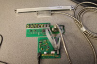
At the back of the picture is the linear encoder connected to the small board which provides level changing because the mcu works at 3,3 v and the encoder works at 5, This connects to the mcu board via 50mil ribbon connectors which provides power to the other two boards and also has test points for scopes etc. The third board is the 8 digit led on which the numbers are just a sanity check at present. The LED is powered by a MAX 7219 ic. The mcu is communicating with the 7219 with SPI protocol.
On the mcu board I have a couple of leds (again as sanity check) blinking in a callback function triggered by the external interrupt caused by the square wave output of the linear encoder.
My next aim is to get the LEDisplay counting in simple terms the impulses from the encoder.
I have now done quite alot of work on the programming, and the whole project is now looking in sight of completion.
I have now got the readout reading 10 micron intervals. I got a bit of help fromAVR FReaks and others concerning using global variables and my whole understanding of C has moved on enormously.
I have also moved on considerably in terms of interrrupts and callbacks. I discovered that the IC port expander which is used in the "From 8 to 32 bits" articles, MCP 23017 has got some superb interrupt facilities and I have run a wire from its interrupt output to the SAMD20 so that I am generally reducing the polling that has to go on in the Main function. I have also created a little library for the IC because I can see it is going to be a very useful chip.
Apart from installing in an enclosure, the principal job left is to be able to use the buttons attached to the MCP 23017 so that I can modify the numbers. For the uninitiated, a digital readout is attached to a machine tool so that cuts can be made with an accurate knowledge of what you are doing, rather than cut and measure, cut and measure. Having measured the work, you set up the numbers on the DRO and you can then do an accurately predictable cut... I hope.
Want to build a project?
Bring your design to life with the Elektor PCB Service, powered by Eurocircuits. Upload the project files and order professionally manufactured PCBs or assembled boards through a proven European production platform.
Supporting KiCad, Eagle, Gerber, and ODB++ formats, the service is suitable for everything from prototypes and validation builds to series production and volume manufacturing.
Made in Europe. Fast. Reliable. Professional.
Discussion (3 commentaire(s))